Procedures
In the following sections, we will provide “How To” checklists for the primary procedures you’ll need to understand to get started in the Hornet.
Cold Start
There are two methods you can use to start a cold and dark Hornet. The first, and easiest, is the Auto-Start. By pressing LWin + Home, the aircraft will be started automatically for you. To cease the Auto-Start, you can press LWin + End.
Being a DCS title though, the Hornet really shines when you take advantage of the detailed systems modeling, like manually starting the aircraft. In this guide, we will skip the Pre-Flight and Upon Entering Cockpit checks and begin with the Before Engine Start checks.
- Set the BATTERY switch to ON and confirm both Left and Right Generators are ON.
RIGHT CONSOLE -
Move and hold the fire detection switch to FIRE TEST A and wait for all the audio caution messages to play. Once complete, wait 10 seconds and then do the same for FIRE TEST B. Between running FIRE TEST A and FIRE TEST B, you can reset the battery switch to rewind the fire test tape.
LEFT CONSOLE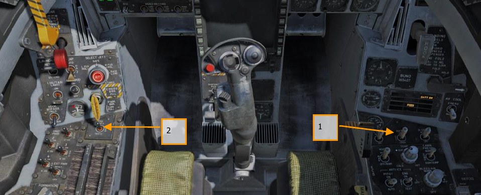
-
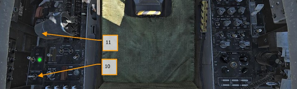
APU switch to ON and wait for green APU READY light.
LEFT CONSOLE - Move the ENG CRANK switch to the right to start the right engine.
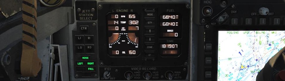
LEFT CONSOLE - Move the right throttle from OFF to IDLE when the right engine is above 25% rpm (as shown on IFEI). RShift + Home
- Once right engine RPM is over 60%, rotate the BLEED AIR knob 360° clockwise, from
NORM to NORM.
RIGHT CONSOLE -
Test the CAUTION, WARNING and ADVISORY lights test.
RIGHT CONSOLE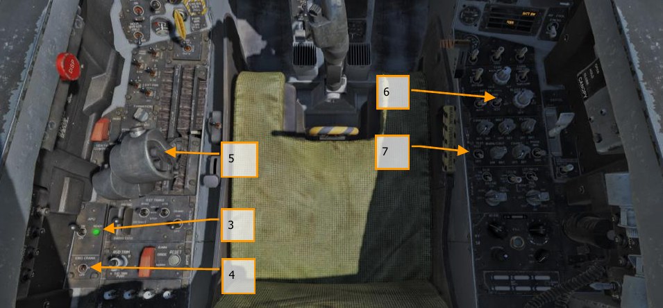
-
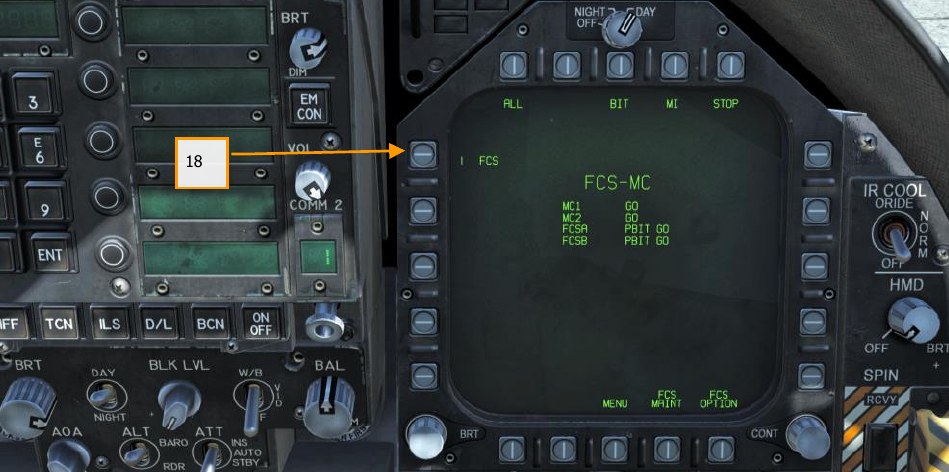
Turn on the power to both DDIs, MPCD and HUD. Select the FCS page on the left DDI and the BIT page on the right DDI.
INSTRUMENT PANEL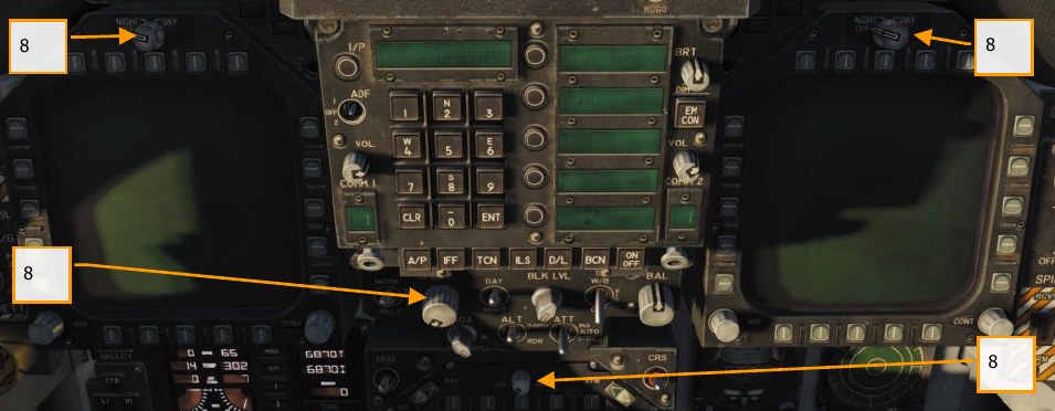
-
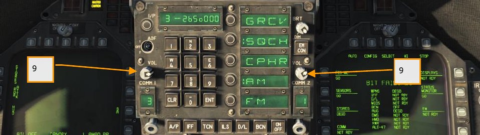
Set COMM 1 and COMM 2 radios as required for the mission.
-
Move the ENG CRANK switch to the left after confirming that the right engine has an rpm between 63 and 70%, a TEMP between 190° and 590°, Fuel Flow between 420 and 900 PPH, a nozzle position between 73 and 84%, and an OIL pressure between 45 and 110 psi.
LEFT CONSOLE -
Move the left throttle from OFF to IDLE when left engine has reached at least 25% rpm by pressing RAlt + Home. [THROTTLES]
-
Once the left engine has an RPM greater than 60%, rotate the INS knob to GND (ground) or CV (carrier), depending on your parking location.
RIGHT CONSOLE -
Set the Radar knob to OPR (operate).
RIGHT CONSOLE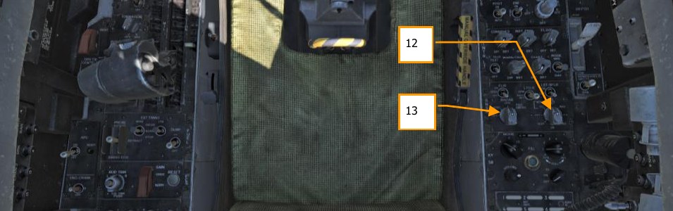
-
Set the OBOGS control switch and FLOW switch to ON.
LEFT CONSOLE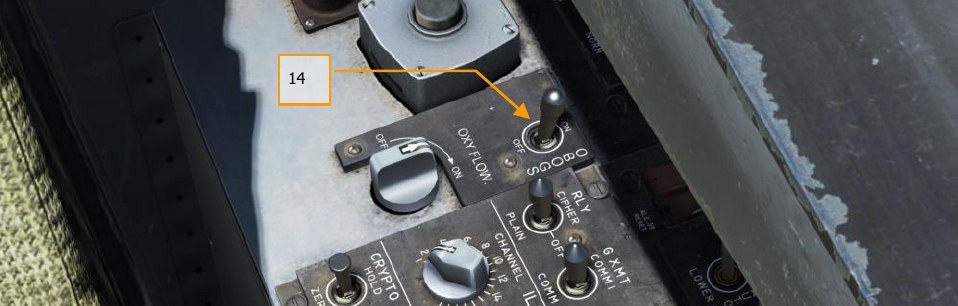
-
Press the FCS RESET button and monitor FCS DDI page.
LEFT CONSOLE - Set the Flap switch to AUTO.
LEFT QUARTER PANEL -
Press Takeoff Trim button.
LEFT CONSOLE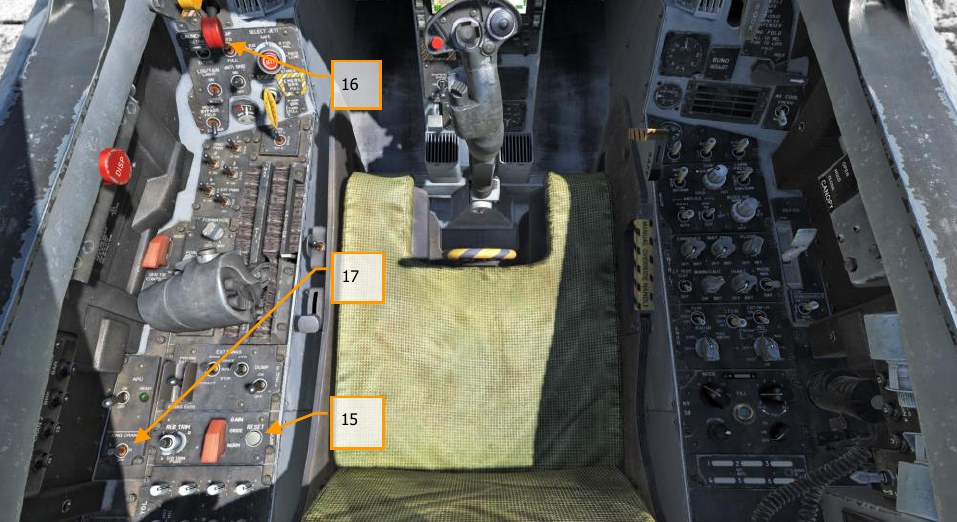
-
While holding up the FCS BIT switch Y on the right wall, press the FCS OSB on the BIT / FCS page at the same time.
-
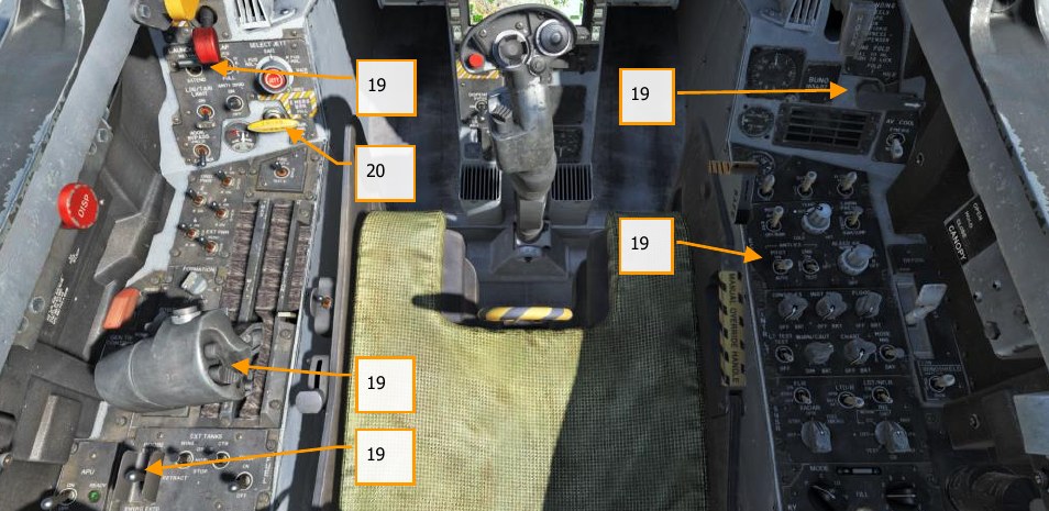
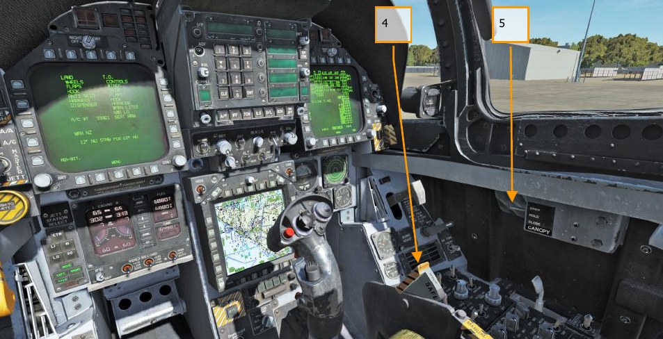
Four down test. Cycle / test the refueling probe, speed brake, launch bar, arrestor hook, pitot heat, and set flaps to HALF.
LEFT CONSOLE, THROTTLES, LEFT QUARTER PANEL, RIGHT QUARTER PANEL, AND RIGHT CONSOLE -
Left mouse click on the hand brake to release it.
-
Set your BINGO fuel level (minimum fuel to return home) by pressing the up and down arrows on the IFEI.
LEFT INSTRUMENT PANEL -
Set the Standby Barometric Altimeter to airfield elevation.
RIGHT INSTRUMENT PANEL -
Set the Radar Altimeter to 200 feet for an airfield takeoff or 40 feet from the carrier. [RIGHT QUARTER PANEL]
-
Uncage the standby Attitude Indicator.
RIGHT INSTRUMENT PANEL -
Set the Attitude Source to AUTO.
CENTER INSTRUMENT PANEL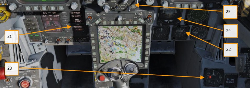
If you plan to use the Joint Helmet Mounted Cueing System (JHMCS), you will need to align it now. To do this, follow the steps in HMD Alignment under the JHMCS chapter.
Airfield Taxi
-
Whether you have completed a cold start or are starting the mission in a “hot” aircraft, your next step will be to taxi to the runway. Slowly advance the throttles PgUp and use the rudder pedals to steer left Z and right X. Reduce throttle by pressing PgDn. Holding down the Noses Wheel Steering (NWS) button, you can enable NWS HI mode enabled tighter taxi turns. Press W to apply wheel brakes.
-
Set the left DDI to the checklist page and the right DDI to the FCS page.
-
At the hold short before entering the active runway: Arm the ejection seat.
RIGHT CONSOLE -
Close the canopy if you have not already done so. LCtrl + C
-
Set the left DDI to the HUD page.
LEFT INSTRUMENT
PANEL
Airfield Takeoff
-
Align the aircraft down the center of the runway and roll forward to align the nosewheel down the runway.
-
Set left DDI to the HUD page.
-
Advance to throttles to afterburner.
-
Use nosewheel steering to maintain a straight track down the runway.
-
At nosewheel rotation speed, hold the control stick back until 6° to 8° nose high attitude (water line above the horizon line on the HUD)
-
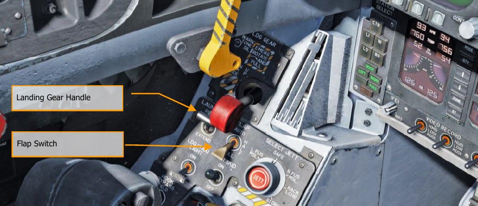
Raise the landing gear and set the FLAP switch to AUTO once positive climb is established.
-
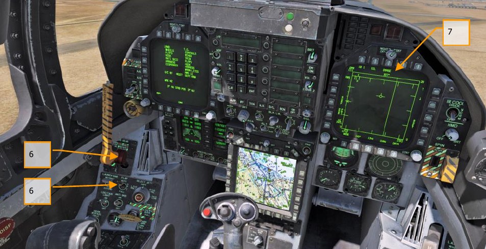
Switch the right DDI to air-to-air radar.
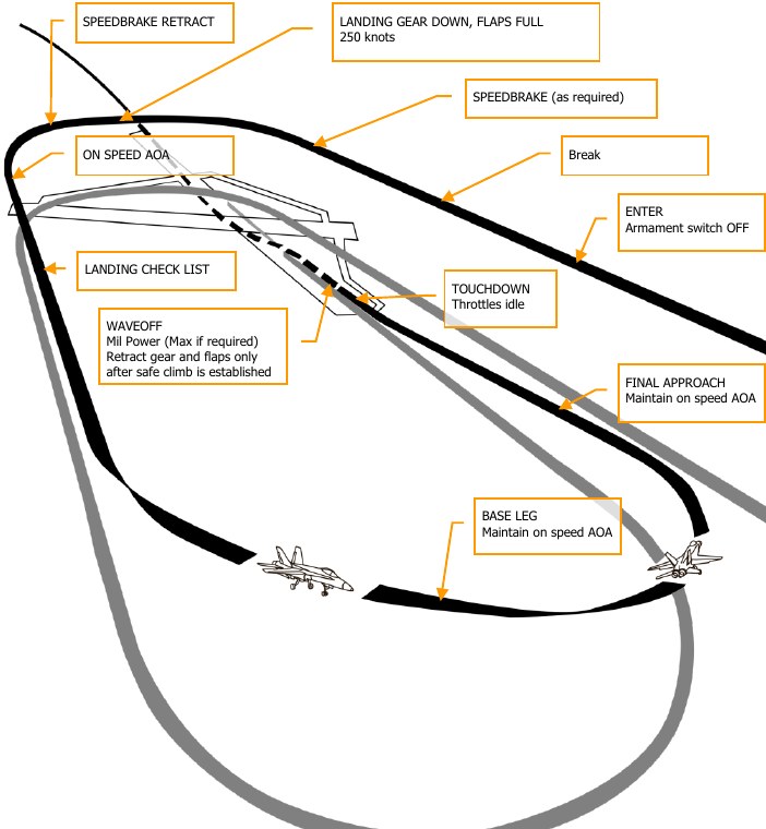
Airfield VFR Landing
Being a carrier-capable aircraft, the Hornet can land on both “the boat” and airfields. Both landing patterns are quite similar. For this guide though, we will just review the procedure for landing at an airfield under Visual Flight Rules (VFR) conditions.
Call up the air-to-air radar page on your right DDI and HUD repeater on your left DDI.
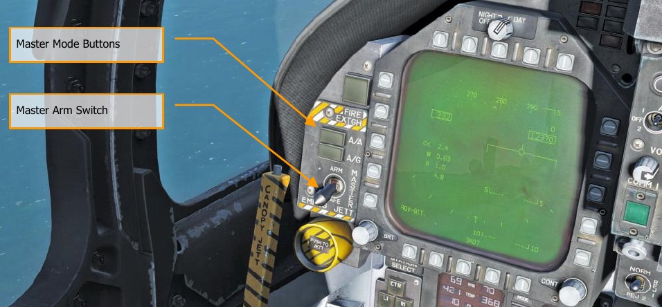
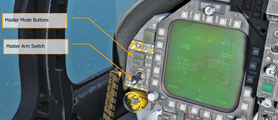
Enter Navigation master mode and set the Master Arm Switch to SAFE on the LEFT INSTRUMENT
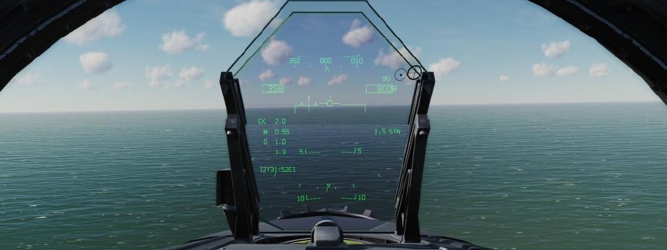
PANEL and approach at 350 knots and 800 feet Above Ground Level (AGL) along the heading of the
landing runway and offset yourself slightly away from your first turn into the pattern.
Five to ten seconds after your wingtip passes the end of the runway (the greater the time, the more time you must establish your on-speed AoA on the downwind leg), turn into the downwind leg of the landing pattern. Generally, pull 1% of your airspeed in g. For example: 350 knots would equal 3.5 g.
Roll out on a reciprocal landing heading and an altitude of 600 feet AGL.
Your lateral offset from the runway should be about 1.2 miles.
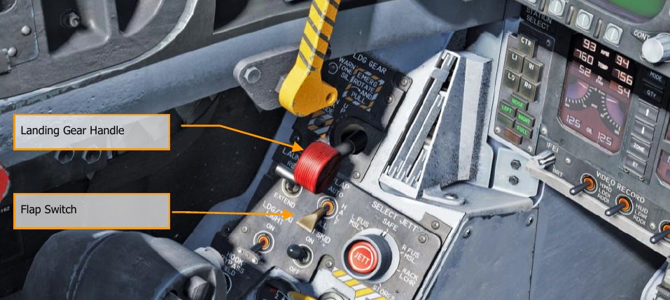
Once your airspeed is below 250 knots, lower your landing gear and place your flaps in the FULL
down position. LEFT QUARTER PANEL
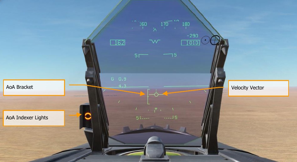
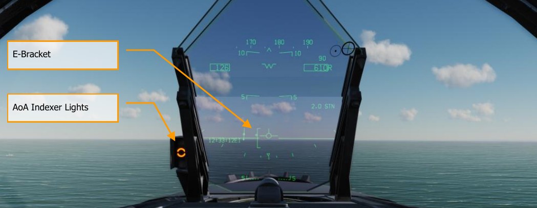
Allow your airspeed to decay until you reach your on-speed angle of attack as indicated left of the HUD on the Angle of Attack Indexer. This will equate to 8.1° of angle of attack which will appear as the yellow circle on the AoA Indexer. On the HUD, the Velocity Vector should be centered in the AoA “E” Bracket. Establish your on-speed AoA at 600 feet AGL.
You will need to trim the aircraft to 8.1° AoA to be hands-free.
Turn into the landing base leg when your wing tip aligns with the runway threshold while maintaining on-speed AoA. Your bank angle should be 30° and the HUD velocity vector should be just below the HUD horizon line. You will need to slightly increase throttle to maintain this AoA. Continue the on- speed descending turn until you are aligned with runway landing heading (a good idea is to set your course line to the landing airfield along the landing runway heading).
Maintain on-speed AoA with the HUD velocity vector placed 500 feet past the runway threshold. Use your throttle to maintain a 3° flight path.
At touchdown, reduce the throttles to idle and use small rudder corrections to stay aligned down the runway roll-out.
Aircraft Carrier Taxi
After completing start up on the carrier, your next task will be to taxi to the catapult for takeoff. The primary difference between an airfield start-up and an aircraft carrier startup will be placing the INS switch in the NORM CVN position for alignment.
Set the left DDI to the checklist page and the right DDI to the FCS page.
Your complete checklist prior to taxi includes:
- Arm the ejection seat
- Check that nosewheel steering is on
- No warning lights
- Hook is up
- Flaps are set to HALF
- Trim set to total aircraft weight
- Wings match wing fold handle
- Oxygen on
- Brake off
- Launch bar up
- Anti-skid off
- Master Arm off
- From the MPCD, select WTPT and cycle the waypoint to 1.
- Countermeasures off
- Radar altimeter to 40 feet
- Canopy closed
- Master external light switch aft
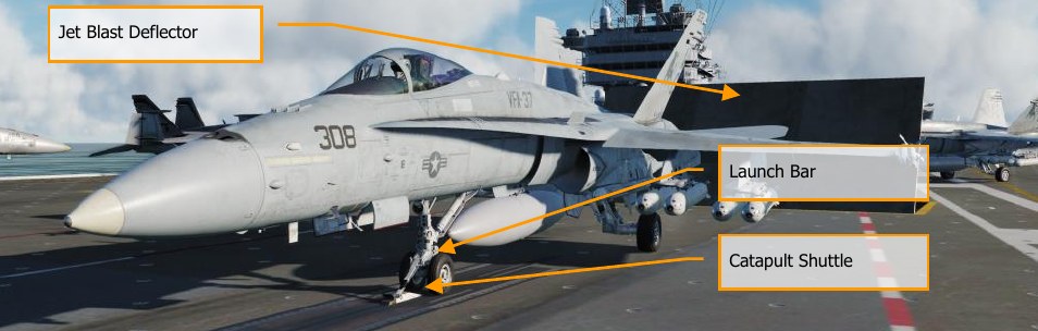
Taxi to the directed catapult using small power inputs while using nosewheel steering in high gain S. Once behind the Jet Blast Defector (JBD) of the catapult you will launch from, spread the wings using the wing fold handle on the right vertical panel. To do so, right mouse button click on the handle until at the SPREAD setting. Then, with the mouse cursor over the handle, rotate forward on the mouse wheel.
Slowly advance the throttles PgUp and use the rudder pedals to steer left Z and right X. Reduce throttle by pressing PgDn. Holding down the Noses Wheel Steering (NWS) button, you can enable NWS HI mode S enabled tighter taxi turns. Press W to apply wheel brakes.
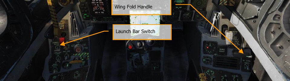
Slowly move forward of the JBD and align your nosewheel along the catapult track. You can best align yourself by using either the F2 external view or taxi to place the shuttle directly left or right of your shoulder when launching from catapult 1 or 2. Once the nosewheel is directly behind the catapult shuttle, lower the launch bar. Next, press U and this will auto-connect the launch bar to the catapult shuttle.
Once hooked up, takeoff stab position with the trim hat based on total aircraft weight. This weight can be seen on the CHECKLIST page. Using the TRIM HAT, set your stabs to takeoff trim based on:
- Below 44,000 gross weight = stab trim 16° (MIL or burners)
- 45,000 to 48,000 gross weight = stab trim 17° (MIL or burners)
- 49,000 and above = stab trim 19° (Burners required)
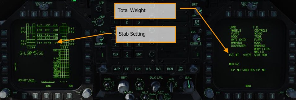
With stabs set to total takeoff weight, you will be ready for launch.
Aircraft Carrier Launch
-
Set throttles to military power and wipe the controls by moving control stick in a full circle and then push full forward and back. Then, push both full left and right rudder.
-
Increase throttle to 100% afterburner and move hand off stick.
-
The catapult will then launch you and place you at flyaway trim.
-
After positive climb rate has been established, raise the landing gear G and set flaps to AUTO F.
-
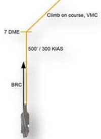
If launching from catapult 1 or 2 (bow catapults), perform a clearing turn to the right and then proceed parallel along the carrier BRC for 7 miles at no more than 500 feet / 350 knots. If launching from catapult 3 or 4 (waist catapults), perform the clearing turn to the left.
-
Set right DDI to the A/A attack radar display.
Case I Carrier Recovery
Landing on aircraft carrier in Case I conditions is much like an airfield in VFR conditions. A Case I condition is defined as visibility of at least 5 miles and clouds no lower than 5,000 feet. In other words, good weather, day light conditions.
Call up the air-to-air radar page on your right DDI and HUD repeater on your left DDI.
Enter Navigation master mode and set the Master Arm Switch to SAFE on the LEFT INSTRUMENT
PANEL. Lower the arrestor hook by pressing H and set HUD altitude to radar.
Entry into the Case I pattern would either be done from a port holding pattern (5 nm diameter circle at 1.5 to 5 thousand feet over the carrier) or a direct approach into the upwind leg. In this guide, we will discuss a direct approach.
Note
For a Case 1 recovery, neither TACAN nor ICLS are required. Those will be discussed in Case II and III recoveries.
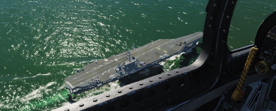
Approach the carrier from astern at 800 feet and 350 KIAS. Pass starboard of the carrier, and just close enough that you can look down to the left and visually spot the carrier deck to make sure the deck is not foul.
At no more than 1.5 nm after passing the bow of the carrier, initiate a level turn to the left.
Generally, pull 1% of your airspeed in g. For example: 350 knots would equal 3.5 g. Roll out on a reciprocal landing heading and an altitude of 600 feet AGL. If your entry speed is above 350 KIAS, you may wish to extend the airbrake until your airspeed decays to 250 KIAS. Once below 150 KIAS, lower the landing gear G and extend flaps to FULL LCtrl + F.
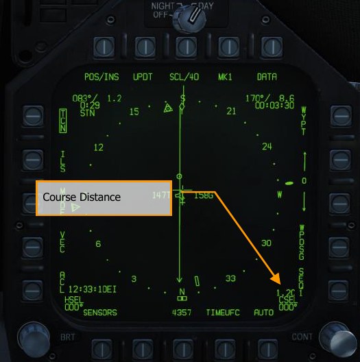
Your lateral course distance from the carrier in the downwind leg should be 1.3 to 1.4 nm. See the TACAN Navigation chapter. \link
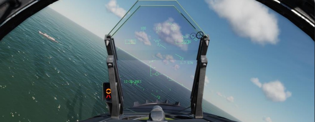
With an established altitude of 600 feet, keep letting airspeed fall until around 145 KIAS and carefully increase throttle such that you capture the on-speed AoA as indicated by the E-Bracket on the HUD and the Angle of Attack Indexer lights to the left of the HUD frame.
Maintain on-speed AoA and 600 feet until the round-down on the stern of the carrier is visible and forms a straight line.

In the first 90 degrees of the second turn, maintain on-speed AoA and use throttle to adjust your decent rate between 100 and 200 feet per minute with a roll angel of 27° to 30°. A good way to visualize this is to place the velocity vector just below the horizon line on the HUD such that just the vertical post and right “wing” touch the horizon line.
During this portion of the turn, don’t peak at the carrier, instead fly by the instruments.
As you pass the second 90 degrees of the second turn, allow your vertical velocity to increase to 500 feet per minute and visually acquire the carrier and Improved Fresnel Lens Optical Landing System (IFLOLS).
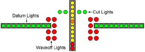
Upon rolling out on final approach to the carrier, all direction is now dictated by the IFLOLS. An optical landing system (OLS) provides the pilot with glidepath information during the final phase of the approach. The first OLS utilized a gyroscopically controlled concave mirror. This mirror was vertically mounted between two horizontal sets of green datum lights. An orange source light was shown in the mirror and would appear as a yellowish orange “ball” to the pilot.
The position of the ball relative to the datum lights would indicate the relative position of the aircraft to the desired glidepath. If the ball was above the datum lights (a high ball), the aircraft was above the glidepath; conversely, a low ball indicated the aircraft was below glidepath. When the ball and the datum lights were aligned horizontally, the aircraft was on glidepath.
The IFLOLS consists of a lens assembly, “cut” lights, waveoff lights, and datum lights. The IFLOLS has three modes of stabilization: Line, Inertial, and Point. Line Stabilization compensates for the ship’s pitch and roll. Inertial Stabilization operates the same as Line Stabilization, but also compensates for the up and down motion (heave) of the flight deck. Both modes stabilize the glideslope to infinity. The point stabilization mode fixes the glideslope around a point 2500 feet aft of the lens. The system is normally set for a 3.5° glideslope targeting the 3-wire. The IFLOLS comes in both the shore-based and ship-based variants.
-
Lens Assembly. The lens assembly is a box that contains 12 vertical cells through which fiber optic light is projected. The upper cells are amber in color while the bottom two are red. The aircraft’s position on the glidepath determines which cell is visible to the pilot. The visible cell, compared to the horizontal green datum lights, indicate the aircraft position relative to the glideslope (i.e., above, on, or below the optimum glideslope). If a red lens is visible, the aircraft is dangerously low.
-
Cut Lights. Mounted horizontally and centered above the lens box are four green cut lights. The cut lights are used by the LSO to communicate with the aircraft during Zip Lip or Emissions Controlled (EMCON) operations. As the aircraft approaches the groove, the LSO will momentarily illuminate the cut lights to indicate a “Roger ball” call. Subsequent illumination of the cut lights indicates a call to add power. Zip Lip is normally used during day Case I fleet operations to minimize radio transmissions. EMCON is a condition where all electronic emissions are minimized.
-
Waveoff Lights. Waveoff lights are mounted vertically on each side of the lens box. These red lights are controlled by the LSO. When they are illuminated, the aircraft must immediately execute a waveoff. The LSO will initiate a waveoff any time the deck is foul (people or equipment in the landing area) or an aircraft is not within safe approach parameters. “Bingo” is signaled by alternating waveoff and cut lights.
-
Datum Lights. Green datum lights are mounted horizontally to the lens assembly with ten lights on each side. The position of the ball in reference to the datum lights provides the pilot with glideslope information. If the ball is illuminated above or below the datums, the aircraft is high or low respectively
Upon the main gears contacting the landing area, immediately move the throttles to full power in case the arrestor hook misses the wires. This will allow the aircraft enough power to get airborne again.
If the “trap” is successful, retard the throttles to idle, raise the arrestor hook H, set flaps to AUTO F and taxi out of the landing area.