Hornet Air-To-Ground (A/G)
The F/A-18 Hornet can employ both guided and unguided weapons, as well as its internal gun. It has the capability to locate and track targets using the onboard radar, ATFLIR, targeting pod, and JHMCS cueing.
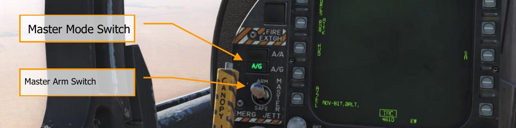
To place the Hornet in A/G mode, first press the A/G button from the Master Mode from the left instrument panel and there must be no weight on wheels. If the Master Arm switch is placed in the SAFE position, weapon release is inhibited, and the SIM training mode is available. When in the ARM position, weapons may be released normally.
Air-to-Ground Radar
As with the Air-to-Air mode, the RADAR switch on the SNSR panel must first be set to the OPR selection. Once supplied power, the operating status will first display NOT READY legend for 30 seconds and then ORT TEST for 2.5 minutes. After 2.5 minutes, TEST is removed and replaced with either STBY, OPR, or EMERG depending on the power switch setting. When airspeed/ground speed is less than 80 knots, the transmitter is inhibited (indicated by Iron Cross).
The radar AG mode can be selected two ways:
- Selection of the AG Master Mode button. AG radar can also be displayed in NAV mode
- Selection of SURF from the radar air-to-air mode puts the radar in MAP mode of the AG radar at a 40 nm range.
Display Controls
As with Air-to-Air mode, TDC assignment is indicated by the diamond symbol in the top right corner of the display. TDC assigned is created using the Sensor Control Switch in the direction of the DDI display the AG radar page.
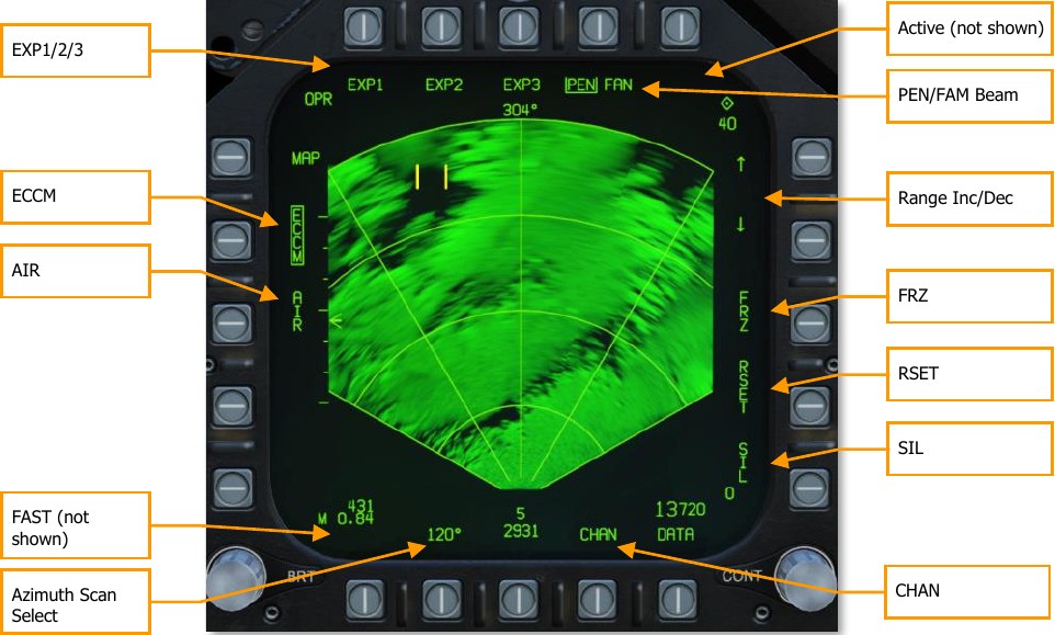
ECCM. This has no function in the simulation and is a static label.
AIR. Pressing the AIR pushbutton puts the radar in air-to-air mode RWS mode.
FAST. When building an image in a DBS mode, selecting FAST decreases the image rendering time three times faster, but reduces the resolution.
Azimuth Scan Select. The azimuth select pushbutton can select azimuth sector scan patters of 20°, 45°, 90°, and 120° with sequential presses. Upon pressing the button at 120°, the selection wraps back to 20°.
SIL (Silent). When selected (boxed), the video display is frozen, the radar does not transmit, displays ACTIVE indication, and the FRZ label is boxed. When disabled (unboxed), the radar resumes normal operation. SIL is not available in PVU and TA modes.
ACTIVE. When in SIL mode, the ACTIVE option is displayed, and when pressed, will complete one antenna scan frame.
RSET (Reset). The reset option is available in the MAP, SEA, GMT, EXP1, EXP2, and EXP3 modes, and when pressed, reinitializes the video gain, pencil or fan beam, and antenna elevation angle for the selected range when no designation or offset has taken place.
FRZ (Freeze). If enabled and SIL is not boxed, the display video is frozen and FRZ is boxed. When deselected (unboxed), the display video is updated normally. FRZ does not stop transmission, only SIL mode will.
When SIL is enabled, selection of the boxed FRZ option will command the radar to blank the video in the display area and the box is removed around FRZ. Video will not be displayed until an active scan is done by either selection of the ACTIVE option or until silent is deselected. FRZ is available in all modes but TA, PVU, and AGR.
Range Increment and Decrement. Up and down arrows are next to the pushbuttons and pressing the up arrow increases range and pressing the down arrow reduces range. Range scales include 5, 10, 20, 40, 80, and 160 nm. Pressing the down arrow with 5 nm selected has no effect and pressing the up arrow with 160 nm selected has no effect. Ranges can be set in the MAP, SEA, GMT, and TA modes.
Range selection is not available if there is an OAP or designated target, and instead will automatically base the range on the OAP or designation when the target exceeds 93 percent/45 percent of the range scale.
Range scale options include:
- MAP - all scales
- SEA - 5, 10, 20, 40, and 80 nm
- GMT - 5, 10, 20, and 40 nm.
- TA - 5 and 10 nm.
- GMT/MAP INTL - 5, 10, 20, and 40 nm
- SEA/MAP - All scales, but targets shown only to 80 nm.
PEN/FAN (Pencil/Fan) Beam. Either a pencil or fan radar beam can be used for the scan by consecutively pressing this pushbutton between PEN and FAN when in MAP, GMT, SEA, EXP1, EXP2, and EXP3 modes. Different modes have different default beam modes. When in MAP, SEA, or GMT modes and the antenna is greater than 5.5° down, FAN mode is automatically selected. If in EXP1 mode, FAN is automatically selected if the angular amount of the ground coverage is greater than 5.5°. In EXP2 and EXP3 modes, PEN mode is boxed, and FAN mode cannot be selected.
EXP1/EXP2/EXP3. When the radar is operating in MAP mode, EXP1, EXP2, and EXP3 options are displayed. If there is no OAP or designation, selecting and EXP mode removes acquisition cursor from the display and the EXP indicator is superimposed on the MAP display. This is termed
MAP W/SECTOR, MAP/PATCH, and MAP W/SAR. The TDC is used to position the EXP scan area on the MAP. This is done by depressing and holding down the TDC switch to slew the EXP area and then releasing the switch to begin the EXP scan and display of the selected MAP area. The selected EXP mode is boxed.
If a designated target or OAP exists, selecting an EXP mode initiates and EXP scan and display that is centered on the target/OAP.
If already in EXP 1 and either EXP 2 or EXP 3 is selected with no OAP or designated target, the EXP 2/EXP 3 scan area is superimposed over the EXP 1 area. This is done by depressing and holding down the TDC switch to slew the EXP area and then releasing the switch to begin the EXP 2/3 scan and display of the selected EXP 1 area.
If already in EXP 1 and either EXP 2 or EXP 3 is selected with an OAP or designated target, the EXP 2/EXP 3 scan is centered on the OAP or designated target.
If already in EXP 3 and EXP 1 or EXP 2 is selected, an EXP 1 scan is initiated that is centered on the EXP 3 area.
EXP 1 and 2 are limited to 40 nm and EXP 3 is limited to 30 nm.
AG Radar Display
The AG radar display consists of the following elements:
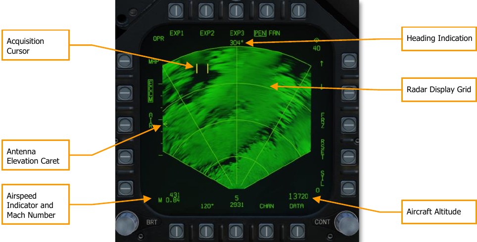
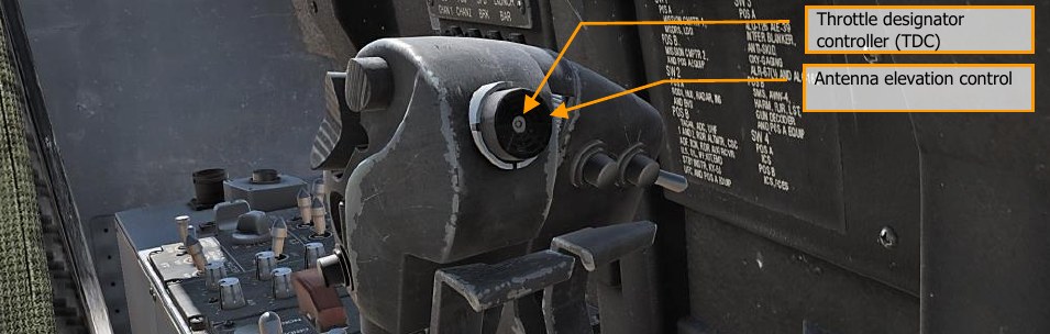
Antenna Elevation Caret. This caret indicates the radar antenna elevation in the vertical plane. It is pitch and roll stabilized to the aircraft’s own horizon. The elevation is controlled by the radar elevation control on the throttle.
Radar Display Grid. The azimuth and range grid lines and range arcs are displayed in the tactical area and are displayed at 0°, ±30°, and ±60°. The four range arcs are separate the range setting into four equal range segments. When in an EXP mode, the expanded areas cover 45° in azimuth for EXP1 an EXP2 covers 12° in azimuth. Coverage of EXP3 is based on range.
Acquisition Cursor. This cursor consists of two parallel, vertical lines and is the same symbol as the air-to-air radar TDC cursor. It can be used in the non-tactical area to select options and designate in the tactical area. It has both slew and press/release functions. When the radar is in a tracking mode, the cursor is no longer visible.
Aircraft Altitude. In the lower right corner of the display, the aircraft’s altitude is displayed in increments of 10 feet. This operates the same as on the air-to-air radar display. Mach Number. The aircraft Mach to the nearest hundredth is displayed in the bottom left corner.
Airspeed Indicator. Calibrated aircraft airspeed is displayed increments of 1 in the lower left corner of the display.
Heading Indication. The aircraft’s magnetic heading is displayed in the top center of the display in the following modes: MAP, SEA, SEA INTL, GMT, GMT INTL, and TA.
HOTAS Controls
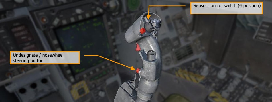
The four HOTAS controls to manipulate the AG radar are the TDC, radar elevation control, the sensor control switch, and the undesignate/nosewheel steering switch. Sensor control switch (4 position)
TDC
If assigned to the AG radar display, it can be used in the non-tactical area to select options. Non- tactical “zones” that the TDC can be placed to display and initiate options include:
- Mode select
- Map gain increase/decrease select
- AIR select
- SURF select
- Azimuth scan select
- SIL select
- RSET select
- Range increment and decrement select
- ACTIVE select
- PEN/FAN select
- EXP1/EXP2/EXP3 select
- INTL select
When in the tactical area while operating in MAP, GMT, or SEA modes, a press and release sets a designation. When pressed, the acquisition cursor is blanked, and the in-video cursor appears. When the TDC switch is released, the stabilized cue is displayed at the in-video cursor intersection. Once a designation is made, the range increment/decrement and the reset options and symbols are removed from the display. Additionally, radar antenna elevation cannot be adjusted.
Radar Elevation Control
When in MAP, GMT and SEA, rotation of this control adjusts the antenna elevation angle.
Sensor Control Switch
This switch is used to assign the TDC to a display. If the radar is on the right DDI and the switch is moved to the right, the TDC is assigned to the right DDI with the radar display, and conversely with the left DDI.
If the TDC is already assigned to the DDI with the radar display, pressing the switch again in the direction of the radar display commands an acquisition on press and a track on the release.
If already tracking, the sensor control switch can be held (pressed) in the direction of the DDI with the radar display, and the TDC can then be used to slew the in-video cursor. Upon release of the sensor select switch, the radar will attempt to track the new location.
If the radar is in track mode, pressing the sensor control switch to the right will break lock on an FTT or GMTT track and the radar will return to search mode (MAP, GMT, or SEA). When the sensor control switch is pressed forward, it assigns the TDC to the HUD and the radar is placed in AGR mode if the radar is not tracking.
Undesignate/Nosewheel Steering Switch
If tracking when pressed, this switch will command the radar back to search mode and undesignate the aimpoint.
AG Radar Search Modes Operation
The master modes of the AG radar include and are cycled by presses of the Mode Select pushbutton (MAP > GMT > SEA > TA > MAP):
- Real Beam Ground Map (MAP). This is the initialized, default mode.
- Ground Moving Target (GMT)
- Sea Surface Search (SEA)
- Terrain Avoidance (TA) later in early access.
Other modes and sub-modes include:
- GMT/MAP Interleave (INTL)
- SEA/MAP INTL
- Doppler Beam Sharpening (DBS)
- Expand 1 (EXP1) Sector
- Expand 2 (EXP2) Patch
- Expand 3 (EXP3) SAR
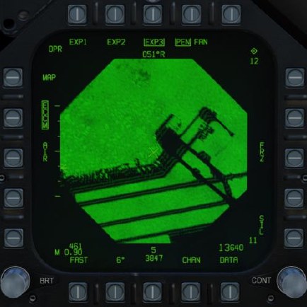
MAP Search Mode
The MAP mode is used to illuminate the terrain and acquire large discrete ground objects. It can rapidly map large areas to identify landmarks for designation. Returns are displayed over eight, separate intensity levels to create a picture. The picture is created by radar reflections off the terrain and objects and back into the antenna for processing. MAP is displayed in a PPI format with zero range at the bottom of the display and the range setting at the top of the display. Lateral displacement of returns is from the centerline of the aircraft.
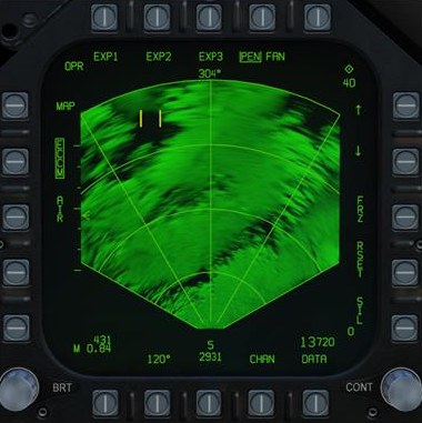
Possible azimuth settings include 20°, 45°, 90°, and 120°. Range setting are from 5 to 160 nm.
The antenna scan is pitch and roll stabilized.
EXP Modes
From MAP mode, EXP1, EXP2, and EXP3 Doppler beam sharpening modes can be selected from the top option buttons.
As the radar first scans the selected region, it builds the first frame. With each new frame, the image is updated which can take several seconds. The time to create a frame is inversely proportional to the angle of track and can vary from 3 to 8 seconds (the closer the frame is to aircraft heading, the longer it will take). However, the FAST option can be enabled to decrease frame creation time, but image quality will suffer.
EXP1 provides a higher resolution picture of a selected MAP sector.
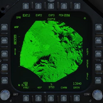
As noted earlier, the EXP1 azimuth is 45° and EXP2 is 12.6°. Due to Doppler frequency shift, the mapped areas to the side of the picture will be better formed than those directly in front of the aircraft. As such, DBS maps (EXP1 and EXP2) are generally created to the side of the aircraft heading.
EXP2 provides the next highest resolution of a small area.
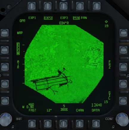
EXP3 provides the highest resolution and uses Synthetic Aperture Radar (SAR) processing to create the image.
When EXP3, the display is converted to a B-scan format (square), the top of the display is still oriented toward the relative direction of the patch being mapped. The maximum and minimum ranges covered in the sector/patch are displayed in the top and bottom of the radar display on the right side of the DDI.
If in EXP3 and the range to a designated stabilized target is less than 5.7 nm, the display changes to EXP2. If the range is then less than 3.0 nm, EXP1 is automatically selected.
GMT and GMTT Modes
The Ground Moving Target (GMT) mode scans for and highlights moving targets, detected by their Doppler shift. Detected targets are displayed as bricks:
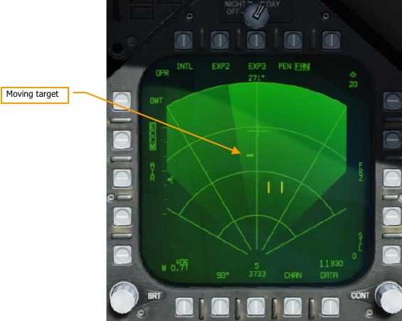
The shaded area of the display shows antenna azimuth coverage.
Moving the TDC over the target brick and pressing the SCS in the direction of the MPCD will command acquisition of the target. Releasing the SCS will command track. The radar mode will change to Ground Moving Target Track (GMTT) and additional target information will be displayed:
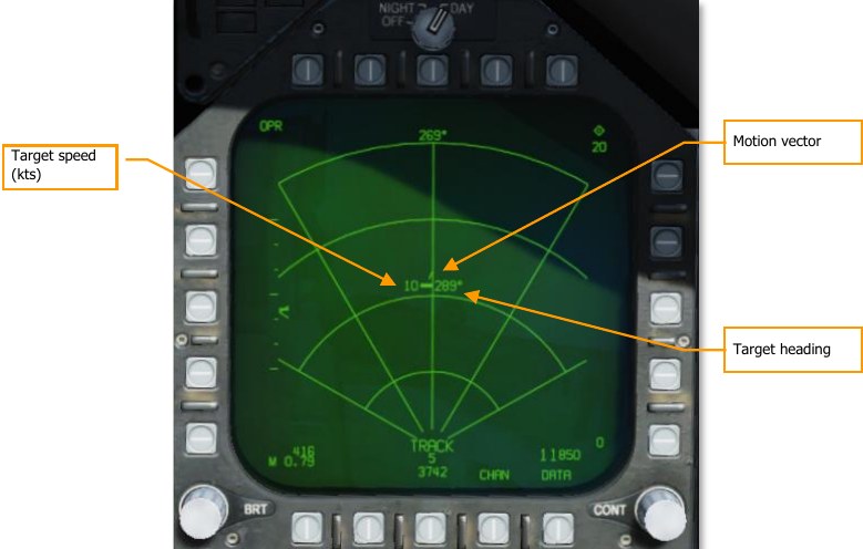
Pressing the Undesignate button will return the radar to GMT mode.
The GMT and MAP modes can be interleaved by pressing the INTL pushbutton (PB 6). The mode will change to GMT/MAP, and the radar will alternate between MAP and GMT modes. Moving targets will be overlayed on the map.
The GMT radar mode can be used in 5, 10, 20, and 40 nautical mile ranges. GMTT is effective out to about 10 nautical miles.
SEA Mode
The SEA mode is suitable for detecting ships and small islands at low sea states. Filtering is applied, scan rate is reduced, and target integration time is lengthened to compensate for scattering caused by the sea surface.
SEA mode uses the same symbology and HOTAS commands as GMT and GMTT modes (documented above). Ranges of 5, 10, 20, 40, and 80 nautical miles are available. SEA/MAP interleaved mode is available just as with GMT/MAP. In SEA/MAP mode, the 160 NM range is available for mapping, but seaborne targets will only be presented out to 80 nautical miles.
A/G Ranging (AGR) Mode
AGR mode is not manually selected, but rather enabled by the Mission Computer automatically under the following conditions:
- When A/G master mode and the TDC is assigned to the HUD with bombs, rockets, or guns selected while in CCIP mode.
- When in NAV or A/G master modes when a HUD, FLIR, or TGP designation is made.
- When in NAV or A/G master modes when AGM-65 is in track mode and the TDC is assigned to the HUD.
In these cases, the radar in AGR mode is providing the ranging information to the MC for weapon employment calculations. The radar is slaved to the gun or rocket reticle, CCIP impact point of the bomb, or FLIR LOS.
On the display, the target range is displayed in feet, and the velocity (VEL) error is displayed. The error in knots is the difference between the target closing velocity measure by the radar and the best available aircraft velocity measured along the radar LOS. Although AGR is displayed next to the mode button, the button has no function when in AGR mode.
Radar Tracking Designations
Offset Aim Points (OAP) and targets can be designated manually on the radar display that include navigation stabilized cursor designation and radar track designation. Radar track designations are only available in MAP, SEA and GMT modes. Navigation stabilized cursor designation is available in all modes.
A designation that is less than 10 nm will become a stabilized cue. If the stabilized cue is outside the radar azimuth, it is removed.
Navigation Stabilized Cursor Designation
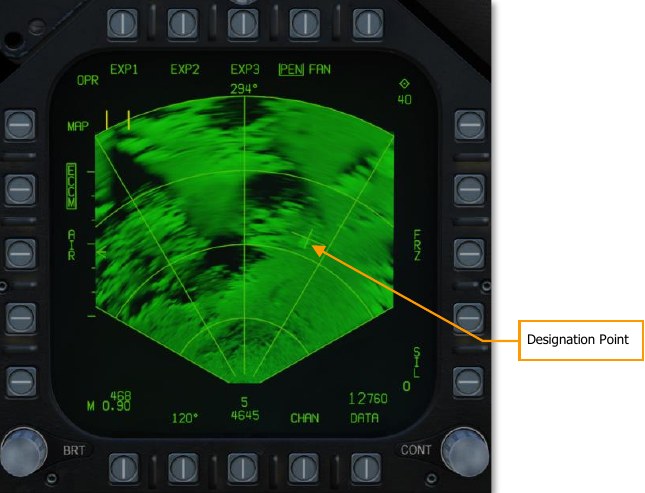
When in any of the modes, the TDC can slew the acquisition cursor (two parallel, vertical lines) on the display. Once the TDC is depressed and held, the designation cursor (intersection of range and azimuth lines that span the entire tactical area) replaces it. Designation Cursor
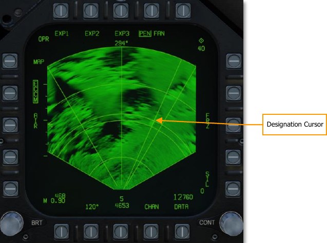
While the TDC switch is held depressed, the designation cursor can be slewed with the TDC. When the TDC switch is released, the designation cursor is designated and stabilized and is replaced with the stabilized cue. The acquisition cursor also now reappears and can be slewed with the TDC.
This process creates a designation point from which an AUTO attack could be initiated. And is also indicated on the HUD as the designation point and steering indicator on the heading tape.
When a designation is made, the range increment and decrement options are no longer displayed, and the display will automatically adjust display range scale to keep the stabilized cue within 93%/45% of the selected range scale. The antenna elevation cannot be adjusted with a stabilized cue and the RSET option is removed.
With a stabilized cue with a weapon in AUTO mode, the weapon Time to Release is also displayed to match the HUD.
Air-to-Ground Markpoints
In both Nav and air-to-ground mode, the F/A-18 Hornet can designate markpoints, locations on the ground which are remembered for later use. Markpoints can be used to designate locations or targets of interest and are effectively the same as waypoints: they can be navigated to or designated for weapons employment.
The Hornet can store up to nine markpoints, labeled MK1 through MK9. MK1 is used following power- on with weight on wheels, then each subsequent markpoint designation is stored in MK2, MK3, and so on. After MK9 is stored, the next markpoint designation is written to MK1, overwriting the previously stored value.
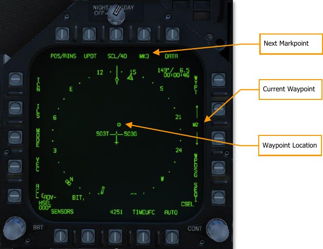
Next Markpoint. Displays the next markpoint to be stored. Pressing this pushbutton stores a markpoint.
Current Waypoint. Shows the current waypoint. The up and down arrows cycle through waypoints. Markpoints are placed in sequence after the last waypoint, WP59. Cycling down from WP0 selects MK9 and cycling up from WP59 selects MK1.
Designating Markpoints
To designate a markpoint, press PB8 (labeled “MK#”) on the HSI format. The location will be stored in the markpoint number that was previously shown adjacent the pushbutton, and the markpoint number will increment by one.
The current target designation will determine what type of markpoint is stored:
Overfly markpoint: To create an overfly markpoint (a markpoint at the current aircraft location), ensure that there is no target designation on any format.
Waypoint markpoint: To create a markpoint at the location of a waypoint, designate the waypoint by selecting it and then boxing WYPT (PB11) on the HSI format.
Air-to-ground radar markpoint: To create a markpoint using the air-to-ground radar, slew the radar cursor to the location you wish to mark, then press the TDC to designate it. On the HSI format, press the MK# pushbutton to create a markpoint at that location. You can then press the pinky button to undesignate the radar target.
Targeting pod markpoint: To create a markpoint using the targeting pod, slew the pod LOS to the location you wish to mark, then press the TDC to designate it. On the HSI format, press the MK# pushbutton to create a markpoint at that location. You can then press the pinky button to undesignate the FLIR target.
Getting Markpoint Coordinates
You may need to relay the coordinates of a markpoint to other players, e.g., if you locate and mark a target that you need assistance destroying.
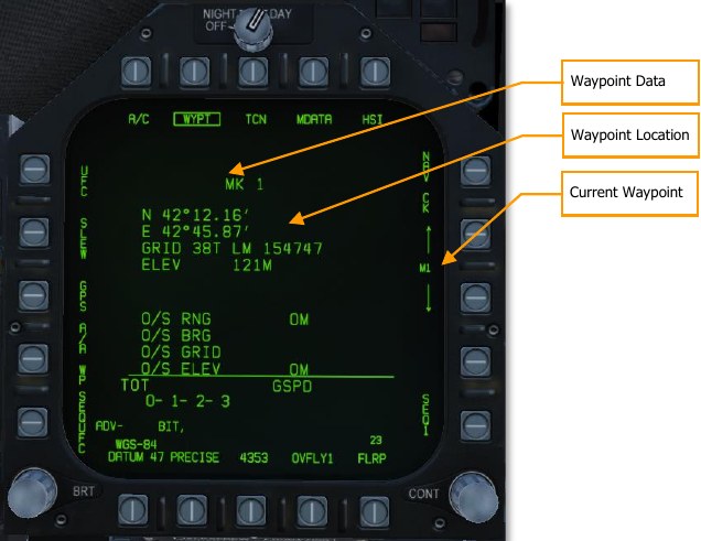
You can retrieve markpoint coordinates the same way you retrieve waypoint coordinates. From the HSI format, press PB10 (labeled DATA) to navigate to the data sub-view. Ensure that PB7 (labeled WYPT) is boxed and use the up/down arrows (PB12 and 13) to navigate to the markpoint. (Remember, the markpoints are stored after WP59 and before WP0.)
Once the proper markpoint is selected, the latitude, longitude, MGRS coordinates, and elevation will be shown on the data page. You can box PRECISE (PB19) to display more precise coordinate data.
Navigating to Markpoints
Markpoints can be navigated to just like waypoints. (However, you cannot add markpoints to a waypoint sequence.)
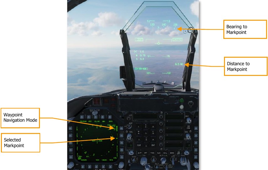
To navigate to a markpoint, select it from the HSI format using the up/down arrows adjacent PB12 and 13. (Remember, the markpoints are stored after WP59 and before WP0.) When the desired markpoint is selected, press PB11 to box WYPT and set the markpoint as the navigation destination.
The upper-left datablock on the HSI will show your bearing, distance, and time to the markpoint, and the HUD will show your bearing to the markpoint along the heading tape, and the distance to the markpoint on the lower-left datablock. If you wish to fly a specific course to the markpoint, use the CSEL switch to set the desired inbound course. See Waypoint Navigation for more information.
Air-to-Ground SMS Bombing Page
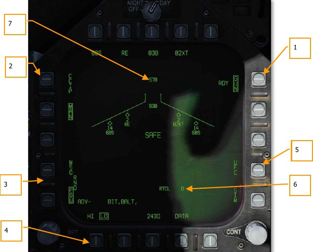
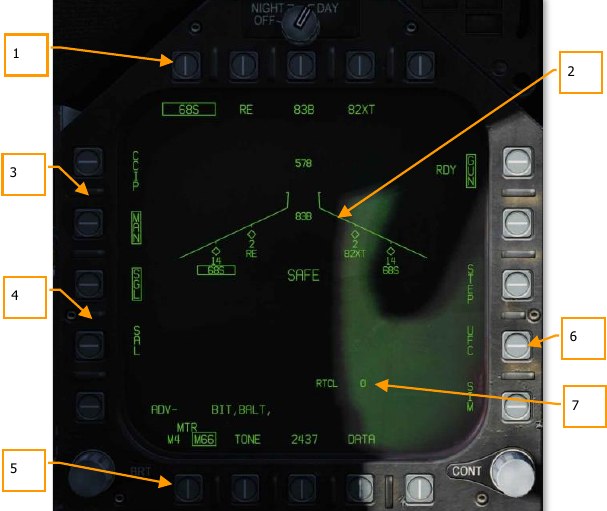
Upon selection of the A/G master mode, the A/G SMS page is displayed on the left DDI. Based on the priority weapon, the information on the SMS page can vary. For conventional bombs, the SMS commonly includes the following:
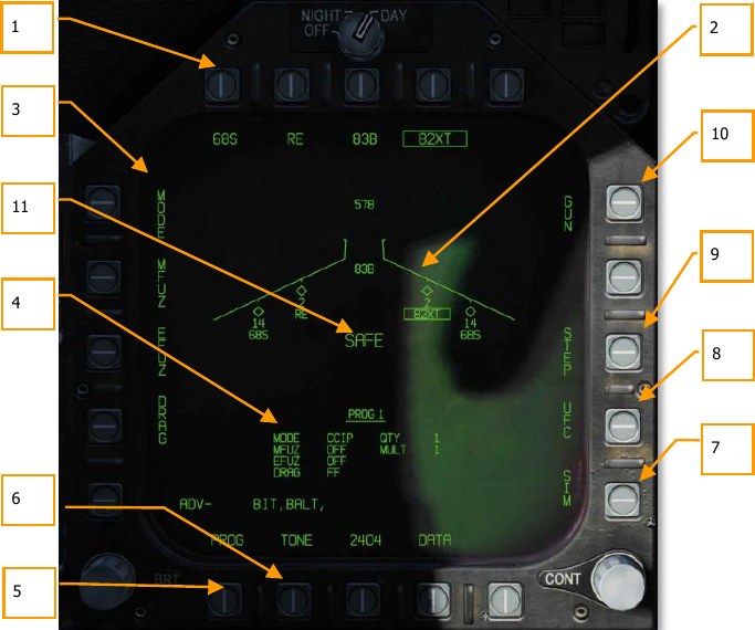
- Weapon Select Options. The top row of pushbuttons is used to select the desired A/G weapon. One option is provided for each displayed weapon type (maximum 5). An abbreviation of the selected weapon type is displayed below the pushbutton. When a weapon is selected, the abbreviation is boxed. Pressing the button again will unselect the weapon. If the A/G weapon is in a release condition, “RDY” is displayed below the weapon box. Otherwise, an “X” is displayed through the weapon box.
- Wingform Display. The wingform display provides the number, type, and status of all stores loaded on the aircraft’s weapon stations. A weapons rack is indicated as a diamond symbol, and the number below indicates the number of weapons loaded on the rack / station. Various indications can be displayed below the number of weapons numeric to indicate weapon status, such as: RDY (ready), STBY (standby), selected (SEL), LKD (locked) and ULK (unlocked). A box is displayed around the weapon abbreviation on the wingform when it is selected as the priority weapon. The gun rounds remaining is indicated at the top of the wingform (578 being a full load and XXX when empty).
- Delivery Program Options. Based on the selected weapon, it may have different delivery options that can be adjusted using these pushbuttons along the left side of the display. Pressing a program button then displays the possible settings for that program option. This will be discussed ahead in the A/G Stores Programming section of this guide.
- Program Data. This area of the display is provided to show release settings as set in the Delivery Program Options for conventional and laser-guided bombs. When a Program contains invalid data, the PROG and number will have an “X” through it.
- Program Select Option (PROG). This option is only available for conventional and laser- guided bombs and allows the selection of five release programs for each weapon type. Successive presses of the PROG pushbutton cycle through the programs. The selected program is displayed at the top of the Program Data. Any changes to the program data for a program are saved and can be retried later when the program is re-selected.
- Tone Option. Cycles between TONE1, TONE2, and unboxed. When boxed, a tone is played over the COMM1 (TONE1) or COMM2 (TONE2) radio whenever the Master Arm is on and the Weapon Release button is pressed.
- SIM Mode Option. When the Master Arm Switch is set to SAFE, the SIM option becomes available. SIM mode allows simulated SMS page and HUD operations, but all weapon release functions are inhibited. When in SIM mode, SIM replaces the ARM/SAFE indication on the A/G SMS page.
- Up-Front Control (UFC) Option. This option is displayed when the selected weapon can have data entered for it using the UFC like weapon release quantity, interval, etc.
- Station Step Option (STEP). The option is provided when the Stores page determines that the weapons of the selected type are available for release on more than one weapon station. Each successive press of the STEP push tile changes the selected weapon to the next weapon station.
- Gun Option. The GUN option is used to select the gun as the priority A/G weapon or enable the gun to be used in conjunction with delivery of another weapon (HOT GUN).
- Master Arm Status. This displays the status of the Master Arm switch, and can be either ARM, SAFE or SIM.
A/G Stores Programming
Programming A/G stores can be done from either A/G or NAV master modes. Up to five delivery programs can be created for each A/G weapon except the gun. Using the PROG pushbutton, you can cycle through the programs with successive presses. There are two primary aspects of creating a delivery program for a weapon: The Delivery Program Options along the left side of the SMS page and the UFC.
Delivery Program Options
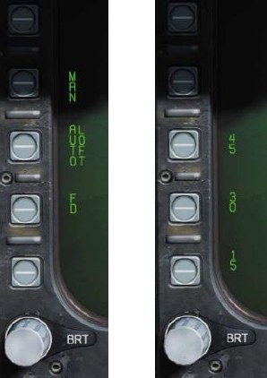
After selecting a Delivery Program Option, the left side of the SMS page will change the pushbuttons to show the possible selections for the selected option:
- MODE (Delivery Mode)
- AUTO (Automatic)
- FD (Flight Director) (N/I)
- CCIP (Continuously Computed Impact Point)
- MAN (Manual Release)
- MFUZ (Mechanical Fuse)
- OFF
- NOSE (Nose Fuse Only)
- TAIL (Tail Fuse Only)
- NT (Nose and Tail)
- EFUZ (Electronic Fuse)
- OFF
- VT (Variable Time or Proximity)
- INST (Instantaneous)
- DLY1 (Delay 1)
- DLY2 (Delay 2)
- DRAG
- FF (Free Fall)
- RET (Retarded)
Bomb Fuze Settings. Different types of bombs require different MFUZ and EFUZ settings. In the current early access, the following should be used:
General Purpose Bombs (Mk-80 series):
- MFUZE = NOSE
- EFUZ = INST
Canister Munitions (CBU and Mk-20)
- MFUZE = VT
- HT to 1500
- EFUZ = INST
Laser and GPS Guided (GBU series)
- MFUZE = OFF
- EFUZ = INST or DLY1
HT Option. The Mk-20, CBU-99, and CBU-100 canister weapons default to using FMU-140 fuses. This is a fixed-setting fuse with an arming time of 1.2 seconds after release.
When MFUZ is set to VT though, the HT (height) setting is available. Successive presses of the HT pushbutton cycle through the possible Height of Burst (HOB) settings.
UFC Options
When the UFC pushbutton is selected from the right side the SMS page, bomb program parameters are displayed on the UFC.
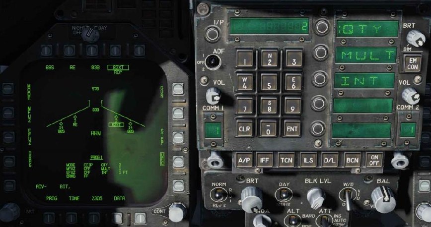
By pressing an Option Select Key on the UFC, you can select the bomb program parameter to enter. The selected parameter is indicated by the colon (“:”) next to the indicator of:
- Quantity (QTY). Number of bombs to release, ranging from 1 to 30. When more than one bomb is selected, you must hold the Weapon Release Button down until all bombs in the salvo are released.
- Multiples (MULT). Number of bombs to be released simultaneously from the weapon stations in each salvo
- Interval (INT). The ground impact spacing in feet when in AUTO, FD, and CCIP modes, but milliseconds when on MAN mode.
After each value is entered using the UFC keypad, the ENTER button on the UFC must be pressed to save the value to the program. Once saved, the value is displayed on the Program Data for the selected program (1 to 5).
Another possible UFC option is the Reticle (RTCL) option. When displayed, you may enter a value in milliradians for manual delivery release. This in turn adjust the bombing reticle on the HUD. This will be discussed in the Manual Bombing section of this guide.
Air-to-Ground Bombing HUD
The HUD has three weapon delivery modes:
- Continuously Computed Impact Point (CCIP)
- Automatic (AUTO)
- Manual (MAN)
Unguided CCIP Bombing Mode HUD
How to Bomb Using CCIP Mode
- Master Mode switch to A/G
- Select a conventional A/G bomb from the SMS page
- Set MODE option to CCIP
- Fly to place the CCIP Bombing Cross over the target while keeping the Velocity Vector above the Pullup Cue
- Press and hold the Weapon Release button
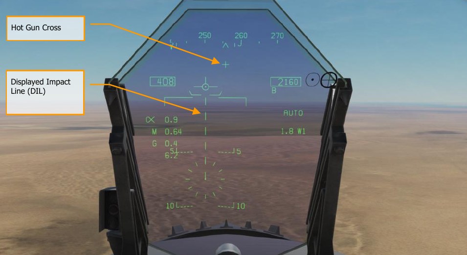
The CCIP mode is a computed visual delivery mode with manual weapon release. This mode allows a high degree of flexibility since the point on the ground at which the weapon will impact is continuously indicated by a CCIP Bombing Cross on the HUD. No target designation is required. In essence, place the thing on the thing and drop the bomb. To use, fly to place the CCIP bombing cross over the intended target and hold the Weapon Release Button down (pickle button). A Displayed Impact Line (DIL) is also on the HUD between the CCIP bombing cross and the velocity vector. The pickle button must be held down until all bombs have been released as part of the program. After bomb release, the Time to Impact (TTI) is presented on the HUD as the Time of Fall (TOF). If the CCIP impact point does not lay within the HUD field of view, the CCIP Reflected Cue is shown as a short, horizonal line on the DIL instead of the CCIP Bombing Cross. The cue is displaced to the same distance above the bottom of the DIL as the computed position of the CCIP Bombing Cross is below the HUD limit.
Elements of the CCIP Bombing HUD include:
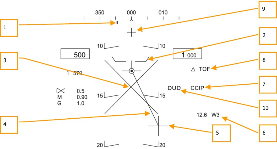
- Steering Point (Command Heading). this pointer on the heading scale provides steering to the selected waypoint or TACAN station.
- Pullup Cue. The distance between the Pull Up Cue and the Velocity Vector provides a relative indication of a safe altitude for delivering the selected weapon. For a safe weapon release, the Pull Up Cue should always be below the Velocity Vector. The Pull Up Cue also provides minimum altitude release for cluster munitions.
- Breakaway X. The flashing Breakaway X will appear on the HUD when a ground collision is imminent, or the DUD cue is visible.
- Displayed Impact Line (DIL). The line between the CCIP Bomb Cross and the Velocity Vector represents the bomb fall line.
- CCIP Bomb Cross. This cross represents the impact point of the bomb(s).
- Waypoint and Distance. Selected waypoint number and distance to the selected waypoint in miles. If in TACAN steering, this would be in relation to the selected TACAN station.
- Mode Indication. The selected bombing mode. CCIP in this situation.
- Time of Fall. Estimated time until weapon impact of the last weapon released. This is indicated in seconds with a “TOF” suffix.
- Hot Gun Cue. Displayed when GUN has been selected from the SMS page. The gun can be fired while in CCIP using the trigger.
-
DUD Bomb Cue. If a canister weapon is selected and the bomb would impact before it would be armed, the DUD Bomb Cue is displayed. The DUD cue will also be displayed if an invalid fuze setting has been selected from the MFUZ and EFUZ settings:
- General Purpose Bombs (Mk-80 series):
- MFUZE = NOSE
- EFUZ = INST
- Canister Munitions (CBU and Mk-20)
- MFUZE = VT
- HT to 1500
- EFUZ = INST
- Laser and GPS Guided (GBU series)
- MFUZE = OFF
- EFUZ = INST or DLY1
-
CCIP Target Designation Option: When in CCIP mode and the TDC is assigned to the HUD, and the CCIP Bombing Cross is within the HUD field of view, pressing the TDC displays the TD on the HUD, which can be slewed within the HUD field of view using the TDC. The TD will initialize on the Velocity Vector or at 7.5°, whichever pitch angle is greater. When the TDC button is released, AUTO bombing mode is entered based on the new target location.
Automatic (AUTO) Bombing Mode HUD
The AUTO mode provides computed, automatic release of bombs. It computes release solutions for dive, dive toss, level, and low angle lofts up to 45°. This mode requires a ground designation point from which to build the bombing solution. Command steering is provided to the appropriate weapon release point and the weapon will release automatically at the proper time such that the weapons hit the target.
To calculate a bombing solution in AUTO mode, a target first must be designated. This can be done by:
- Flying to place the HUD reticle pipper over the target and designate it with the TDC button.
- Designating a waypoint location as the target as set on the HSI using the WPDSG option.
AUTO HUD Designation
The Mission Computer (MC) provides an Azimuth Steering Line (ASL) to provide steering to the designated target. Designation is accomplished pressing and holding the Weapon Release Button when the HUD Reticle is over the target. By placing the Velocity Vector on the ASL and holding down the Weapon Release Button, the weapon will release at the proper time and account for wind.
How to Bomb in AUTO Mode Using the HUD
- Master Mode switch to A/G
- Select conventional A/G bomb from the SMS page
- Set MODE option to AUTO
- Assign TDC to the HUD (Sensor Control Switch forward)
- Fly to place the Reticle over the target and then designate the target by pressing the TDC switch
- While flying to keep the Velocity Vector above the Pullup Cue, keep the Velocity Vector over the Azimuth Steering Line (ASL), and hold the Weapon Release button down when the Release Cue appears on the HUD
- Release the Weapon Release Button once all bombs in the pass have been released Mode Indication
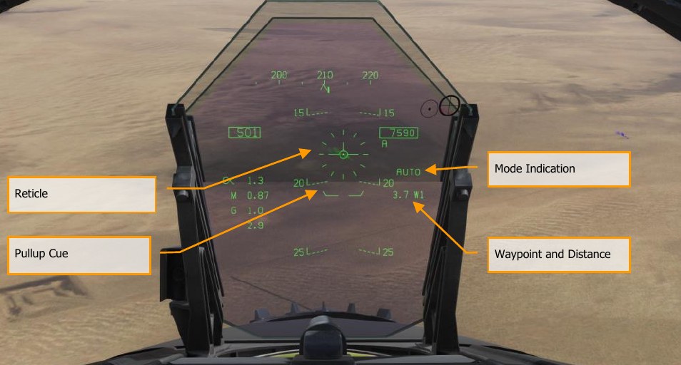
Reticle. This Reticle consists of tic marks in 50-mil diameter circle with a pipper in the center. The TDC must be assigned to the HUD (Sensor Control Switch forward) for the reticle to be visible on the HUD. The Reticle serves as a steering reference for weapon delivery by having the pilot fly the aircraft to place the pipper of the Reticle over the intended target and then designating it.
Pullup Cue. The distance between the Pull Up Cue and the Velocity Vector provides a relative indication of a safe altitude for delivering the selected weapon. For a safe weapon release, the Pull Up Cue should always be below the Velocity Vector. The Pull Up Cue also provides minimum altitude release for cluster munitions. When the Velocity Vector is below the Pullup Cue, the Breakaway X is displayed on the HUD.
Mode Indication. Indication of the selected bombing mode from the Stores page.
Waypoint and Distance. The selected waypoint number and the distance to the waypoint in miles. If the target is co-located with the waypoint, this will also be the Target Distance. This may also be in reference to TACAN steering.
Hot Gun Cue. Displayed when GUN has been selected from the SMS page. The gun can be fired while in AUTO mode using the trigger.
Displayed Impact Line (DIL). The flashing, dashed DIL is displayed on the HUD when dive angle is greater than 7.5°. The DIL extends from the Vertical Velocity indicator to the center of the Reticle.
AUTO Waypoint Designation
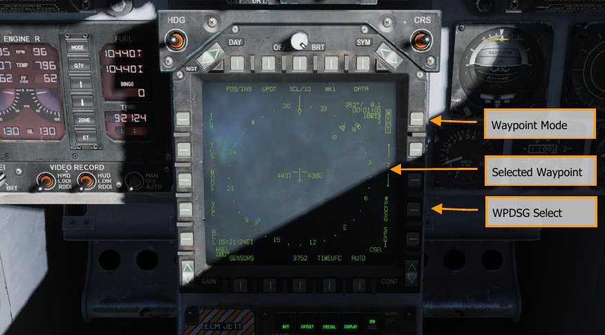
The Mission Computer (MC) provides an Azimuth Steering Line (ASL) to provide steering to the designated target based on a designated waypoint. Designation is accomplished by selecting a waypoint on the HSI and selecting the Waypoint Designation (WPDSG) option on pushbutton 18. This will turn set the selecting waypoint as a target (TGT) waypoint from which the AUTO bomb delivery is calculated.
How to Bomb in AUTO Mode Using a Target Waypoint
- Master Mode switch to A/G
- Select conventional A/G bomb from the SMS page
- Set MODE option to AUTO
- Select the waypoint at the desired target location
- Select WPDSG from HSI to set the waypoint as the TGT
- While flying to keep the Velocity Vector above the Pullup Cue, keep the Velocity Vector over the Azimuth Steering Line (ASL), and hold the Weapon Release button down when the Release Cue appears on the HUD
- Release the Weapon Release Button once all bombs in the pass have been released
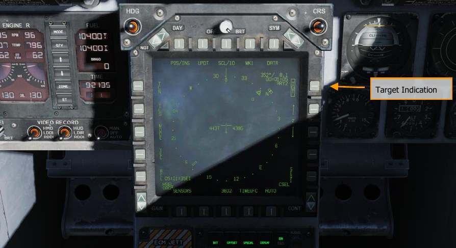
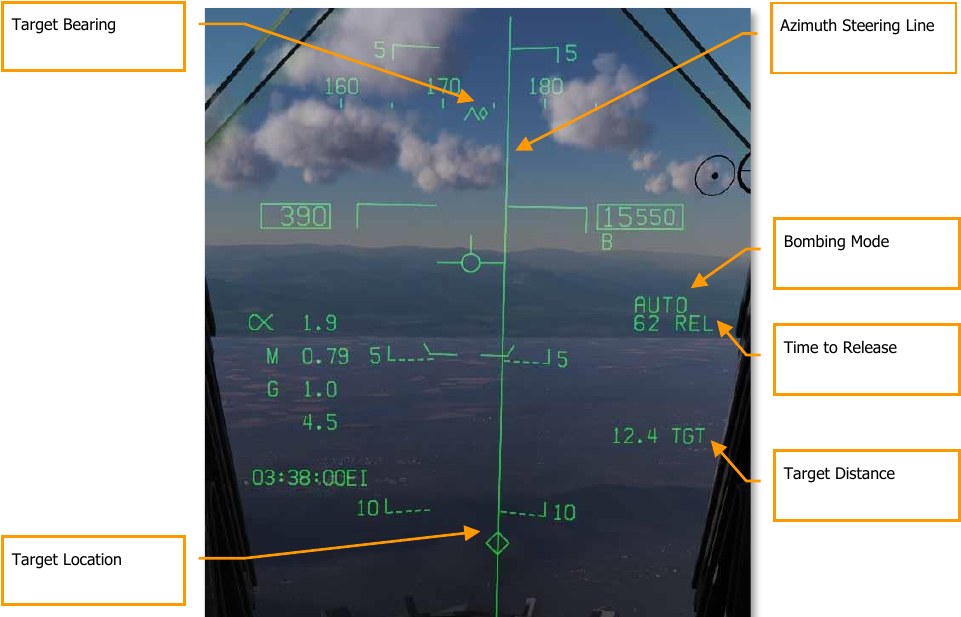
Once a waypoint is designated as a target (TGT), the HUD provides steering directions toward it.
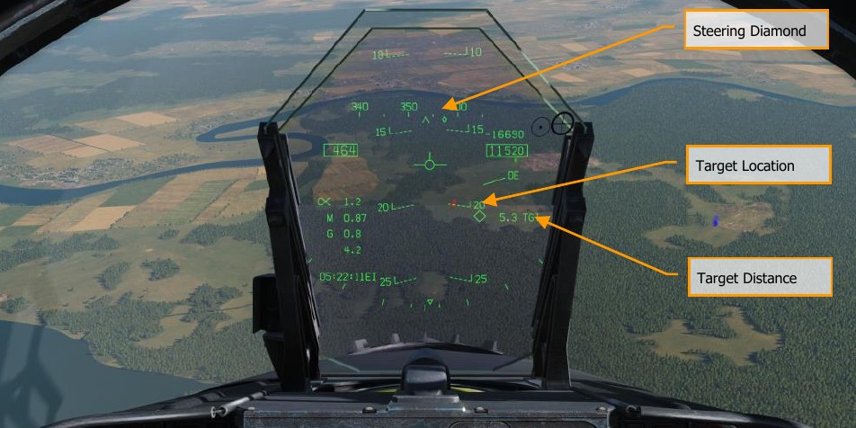
Steering Diamond. Along the heading tape, this diamond indicates the steering direction toward the target location. When flying directly toward the target, this diamond will be in the center of the heading tape.
Target Location. A diamond symbol marks the line-of-sight location to the target. When the location is outside the HUD field of view, this diamond is clamped to the side of the HUD closest to the target and flashes. Note that the location of the target also accounts for the entered elevation of the waypoint from which the target is created.
Target Distance. The distance to the target is indicated at the range in nautical miles.
AUTO Bombing Delivery
Once the target is designated using either the HUD or a waypoint and the SMS page is set for AUTO delivery, the Azimuth Steering Line (ASL) is displayed on the HUD and provides steering direction to the target as indicated by the Steering Pointer on the Heading Scale. When within the HUD field of view, the target will also be marked with a diamond Target Designator that denotes the targets line of sight location. By flying the aircraft to keep the Velocity Vector on the ASL, the aircraft will assume the correct azimuth steering to satisfy the bombing solution. By flying to maintain the Velocity Vector over the Pullup Cue, adequate release altitude is also assured to avoid weapon fragmentation and weapon fuzing.
When the target diamond is dashed, the TDC cursor can be used to move the target location. If a canister weapon is selected and the bomb would impact before it would be armed, the DUD Bomb Cue is displayed.
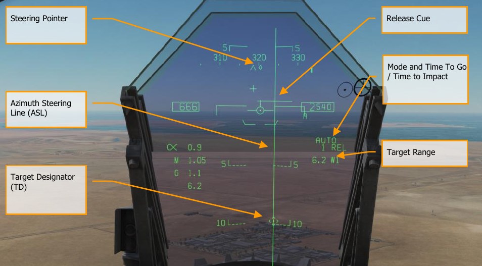
Steering Pointer. Once a target has been designated, the cue changes from a line indicating navigation steering (waypoint or TACAN), to a diamond that indicates steering to the designated target.
Release Cue. This small, horizonal line centered on the ASL is displayed when the target is designated, and it indicates both in-range and release cue anticipation indicator. For high drag bombs, the cue is displayed 5 seconds before release.
Azimuth Steering Line (ASL). The ASL is always perpendicular to the horizon and provides an azimuth steering reference to the designated target with respect to the Velocity Vector. The ASL is removed from the HUD when the target command steering is greater than 90°.
Target Designator (TD). This symbol shows the line of sight to the designated target. The symbol is 9 mils long on each side and has a pipper in the center when the TDC is assigned to the HUD. Using the TDC, the TD can be moved within the HUD field of view (useful when refining a target designation). If the TD is outside the HUD field of view, it is clamped to the nearest side and flashes. The TD is removed from the HUD when the target command steering is greater than 90°.
Time to Go / Time to Impact. Upon target designation, the estimated time to release is indicated in seconds with an “REL” suffix. After the bomb(s) is released, this field indicates the estimated Time to Impact and is indicated in seconds of the last weapon released with a “TTI” suffix.
Target Range. When the target is designated, the range to the target is indicated in miles. Note that when the target is not within the HUD field of view, a target arrow points in the direction of the target and the number of degrees to the target is displayed next to the arrow.
Manual (MAN) Bombing Mode HUD
Manual mode is a backup mode for visual delivery. From the A/G SMS page with MAN selected as the delivery mode, the UFC function allows the pilot to adjust the HUD reticle position in mils. By understanding the bombing table data for a weapon (release angle, altitude, and airspeed), the manual mode can be an effective means to place bombs on target.
How to Bomb Using MAN Mode
- Master Mode switch to A/G
- Select weapon
- Select conventional A/G bomb from SMS page
- Set MODE option to MAN
- Select the UFC Option Select Button on the A/G SMS page and enter the desired mils setting on the UFC using the keypad. When complete, press the ENTER button on the UFC
- Fly to place the Reticle over the target-based bombing table data
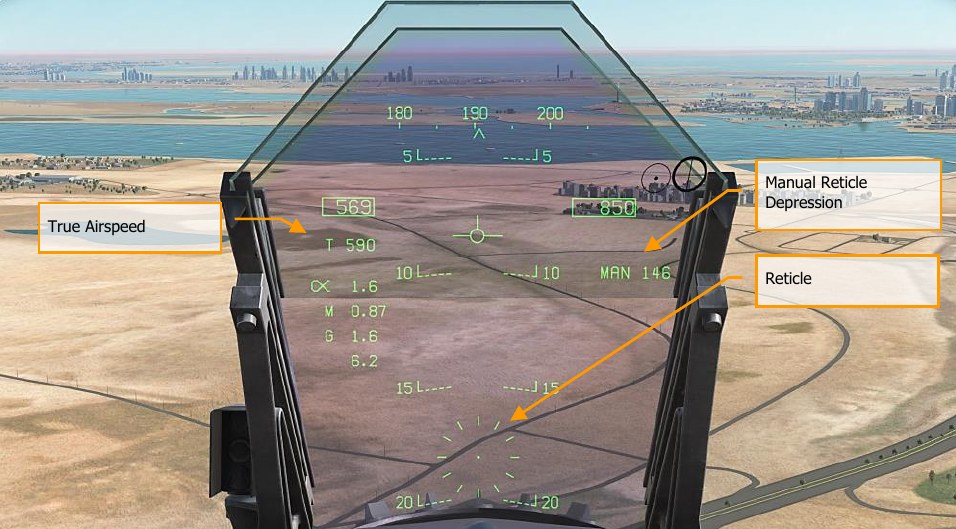
Manual Reticle Depression. Depression of the Reticle in mils based on the UFC input.
Reticle. Fixed Reticle at static position on the HUD based on the manual mils setting.
True Airspeed. When in MAN mode, True Air Speed (T) is displayed below the indicated airspeed box.
High Drag (HD) Bomb Delivery
The Hornet has the option to delivery high drag bombs that either use a ballute chute or fold-out brakes. This allows the bomb to fall well behind the aircraft when dropped at low-altitudes and fast airspeeds. In addition to the high-drag option, these bombs also have “slick” options that allow them to behave as standard free-fall bombs. The Hornet’s high drag bombs include:
- Mk-82 Snake Eye, that is a Mk-82, 500-pound class bomb that has the option for four, fold- out airbrakes to slow the weapon. The SMS code is 82XT.
- MK-82 with BSU-49 ballute is a Mk-82, 500-pound class bomb that uses an inflatable bag that retards the weapon. It SMS code is 82YT.
High drag weapons can be delivered in CCIP, AUTO, and MAN modes.
SMS Set Up
Upon selecting a high drag bomb:
- Set delivery MODE
- Set MFUZE to NOSE
- Set EFUZ to INST
- Set DRAG to FF for free fall or RET for high drag
When DRAG is set to RET, guidelines for an accurate delivery are as follows:
- Ensure that aircraft barometric pressure altimeter match the mission
- Level flight between 300 to 500 feet AGL
- Maintain flight path marker on or just above the horizon line on the HUD. Letting it dip below the horizon line will result in a Break X.
- Airspeed above 450 knots
JHMCS Air-to-Ground Mode
The Joint Helmet-Mounted Cueing System can be used in air-to-ground mode to visually designate targets within the pilot’s line-of-sight. To use the JHMCS in air-to-ground mode, first put the aircraft in A/G Master Mode and verify that the HMD knob is turned up. Then press Castle Switch Forward to move TDC priority to the HMD and HUD.
When the JHMCS is on, Castle Switch forward assigns the TDC to either the HMD or the HUD. TDC assignment then automatically switches between the HMD and the HUD until the TDC is assigned to an MFD. When the pilot LOS is within the HMD blanking area (in other words, generally looking forward towards the HUD), TDC assignment moves to the HUD. When the pilot LOS is outside of the HMD blanking area, TDC assignment moves to the HMD. This is true regardless of whether HMD blanking is turned on or off.
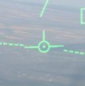
When the TDC is assigned to the HUD, the TVV appears with a dot in the center:
When the pilot’s LOS moves away from the HUD, TDC priority jumps to the HMD, and an aiming reticle appears on the HMD:
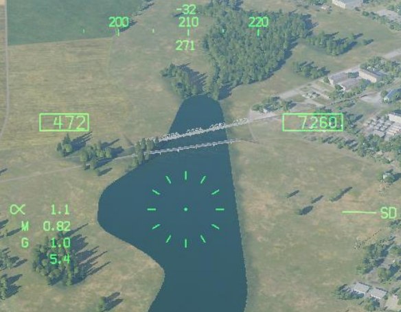
The aiming reticle appears if a) the aircraft is in A/G Master Mode, b) the JHMCS is powered on, c) the pilot LOS is outside the HMD blanking area, and d) there is no current designation. With the aiming reticle visible, pressing TDC Designate creates a designation at pilot line-of-sight. The mission computer calculates best altitude above target (BAAT) to place the TDC on the surface of the earth.
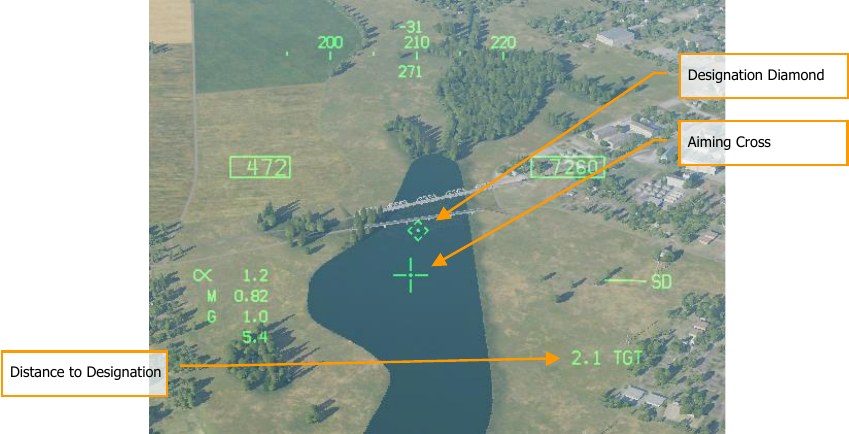
A designation diamond will appear on the surface at the designated location. If the targeting pod is active, pod LOS will automatically slew to the designation LOS. The aiming reticle will change to a smaller cross; a dot will appear in the center of the cross if the HMD still has TDC priority. The designation diamond will have a segmented outline if no-action slew is available; in other words, if the pilot can refine the designation using the TDC immediately. If the designation cannot be slewed (e.g., the FLIR is in a track mode), the diamond will appear solid.
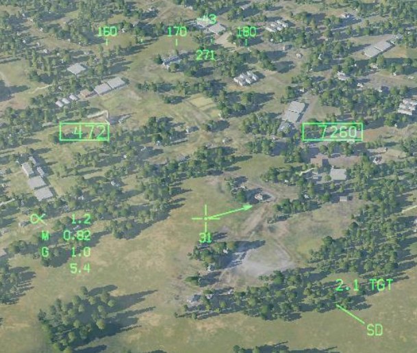
If the designation moves out of the HMD field of view, the aiming cross will gain a target locator line (TLL) pointing in the direction of the designation. A number will appear below the aiming cross indicating the angle between HMD LOS and the designation, in degrees.
Laser-Guided Bombing
Delivery of laser-guided bombs can be conducted in CCIP, AUTO, and MAN modes, but AUTO mode is preferable as it allows delivery while in level flight. Laser-guided bombs should be released at greater than 8,000 feet AGL to give enough time for laser designation capture and guidance.
How to Use Laser-Guided Bombs in AUTO Mode
- Master Mode switch to A/G
- Select weapon
- Select laser-guided bomb from SMS page
- Set MODE option to AUTO
- Set MFUZ to OFF and EFUZ to INST
- Create TGT point to which bomb will guide
- Set laser code of bomb to match designation code
- Align bomb fall line with target bearing and drop bomb when release cue passes through the velocity vector
Two general types of laser-guided bomb units (GBU) can be loaded on the Hornet:
- Paveway II series: GBU-10, GBU-12, and GBU-16
- Paveway III series: GBU-24B/B
Both Paveway series have unique SMS and HUD symbology.
Paveway II Series
Loading
SMS Codes:
- GBU-10: 84LG
- GBU-12: 82LG
- GBU-16: 83LG
Loading:
- A single GBU-10 can be loaded on stations 2, 3, 7, and 8 on a BRU-32.
- A single GBU-12 and 16 can be loaded on stations 2, 3, 7, and 8 on a BRU-32.
- Dual GBU-12s can be loaded on stations 2, 3, 7, and 8 on a BRU-33.
SMS Page
Paveway II series bombs are displayed on the wingform as conventional bombs are. The only difference is that a four-digit laser code is displayed below the weapon code. All Paveway II series bombs show the same code if a Paveway II series bomb is not first selected. If a Paveway II series bomb is selected, the code is just be applied to the priority station bomb. This allows you to set separate laser codes for each bomb.
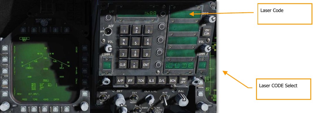
If an LGB is detected as being loaded on the aircraft, the CODE pushbutton will be present on the SMS page at pushbutton 1.
The default laser code is XXXX. To change the code, the CODE legend at pushbutton 1 is pressed when a Paveway II series bomb is already selected. Upon doing so, the bottom Option Select Window shows CODE, and the keypad can be used to enter a four-digit code. Once CODE is colonized, this code should match the designation from a JTAC, targeting pod, or another laser designation source. Once the UFC ENT button is pressed, the code is saved to the SMS and is displayed below one or all Paveway II series bomb.
As with unguided bombs in AUTO, CCIP, and MAN modes, the UFC option can be used to set quantity, interval, and multiple values if desired.
HUD
For Paveway II series bombs, both the AUTO and MAN HUD modes are identical to conventional delivery. The additional data seen in the image below appears to be targeting pod related.
Paveway III Series
The Paveway III-series of laser-guided bombs introduces further enhancements over the Paveway I and Paveway II weapons. Most notably, Paveway III guidance kits eschew traditional “bang-bang” guidance (where the control fins are only fully deflected in one direction or the other) for proportional deflection, where the control fins can move in increments to steer the bomb, giving the bomb longer range. The Paveway III electronics also gives the bomb more guidance capability, which is reflected in updated avionics controls. The GBU-24 is the Paveway III variant with a 2,000-pound warhead (equivalent to a Mk. 84).
The Paveway III computes a launch acceptability region (computed LAR or CLAR). If the bomb is dropped within this region, it can maneuver onto a target that is being lased. To compute the LAR, the Paveway III must know the approximate location of the target being lased (for example, co- located with a designated waypoint). The Paveway III can calculate a “straight-line” LAR, a LAR that assumes the aircraft flies a straight line from its present location directly to the target; or it can calculate a “pre-planned” LAR, which assumes the pilot attacks the target from a pre-determined heading.
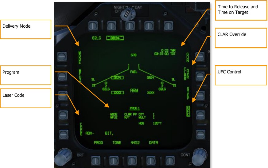
The STORES format for the GBU-24 is like previous-generation laser-guided bombs, with additional options to control Paveway III-specific features.
Delivery Mode. Allows the pilot to choose between CLAR PP (pre-planned computed LAR), CLAR SL (straight-line computed LAR), and MAN (manual) delivery modes.
Program. Displays the release program, including the release mode and the pre-planned heading used by the CLAR PP delivery mode.
Laser Code. Pressing PB1 allows the pilot to use the UFC to set the laser code that the bomb will search for.
Time to Release. When outside the LAR, this line displays the time until reaching the LAR. (TTR is omitted when 10 minutes or greater.) Once inside the LAR, it displays IN ZONE. Displays TOO LOW if the aircraft is below the minimum release altitude.
Time on Target. An estimation of the Zulu time of weapon impact. Only displayed when inside the LAR. After the bomb is released within the LAR, this line is replaced by a time-to-impact countdown.
CLAR Override. Normally, the bomb can only be released when the aircraft is inside the LAR. When this option is boxed, the Weapon Release button is always hot, and post-release lasing is disabled. The CLAR Override option is saved on a per-program basis.
UFC Control. Places program settings on the UFC for the pilot to edit. The UFC will display the program settings common to all bombs (quantity, multiples, interval), as well as a CLAR option that allows the pilot to enter the pre-planned attack heading.
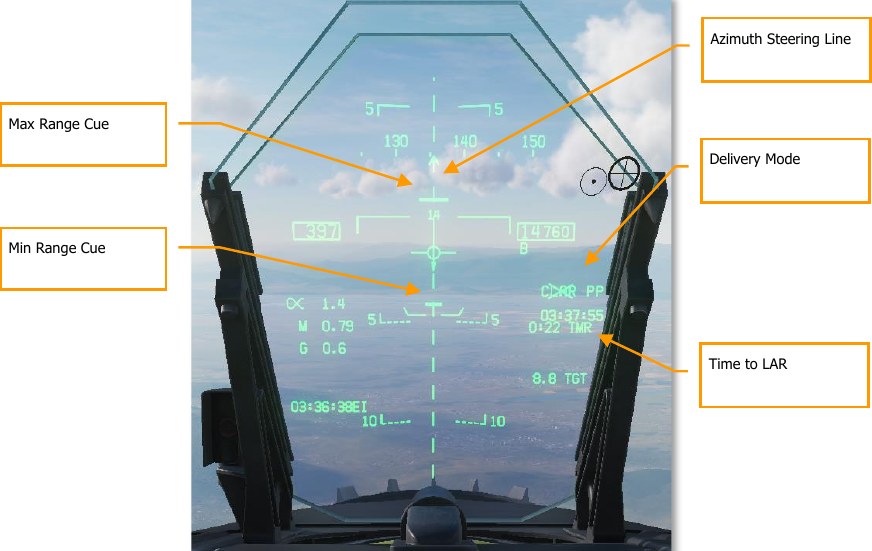
Azimuth Steering Line. Displayed as dashed when outside LAR. Becomes solid when inside LAR, or when CLAR OVR is selected (making the Weapon Release button hot).
Time to LAR. Identical to the STORES page indication; displays the time until penetrating the LAR, or IN ZONE when in the LAR, or TOO LOW when below the minimum release altitude.
Min/Max Range Cue. Represents the minimum and maximum extent of the LAR along the attack axis. These cues flash when the aircraft is within 1,000 feet of the minimum release altitude.
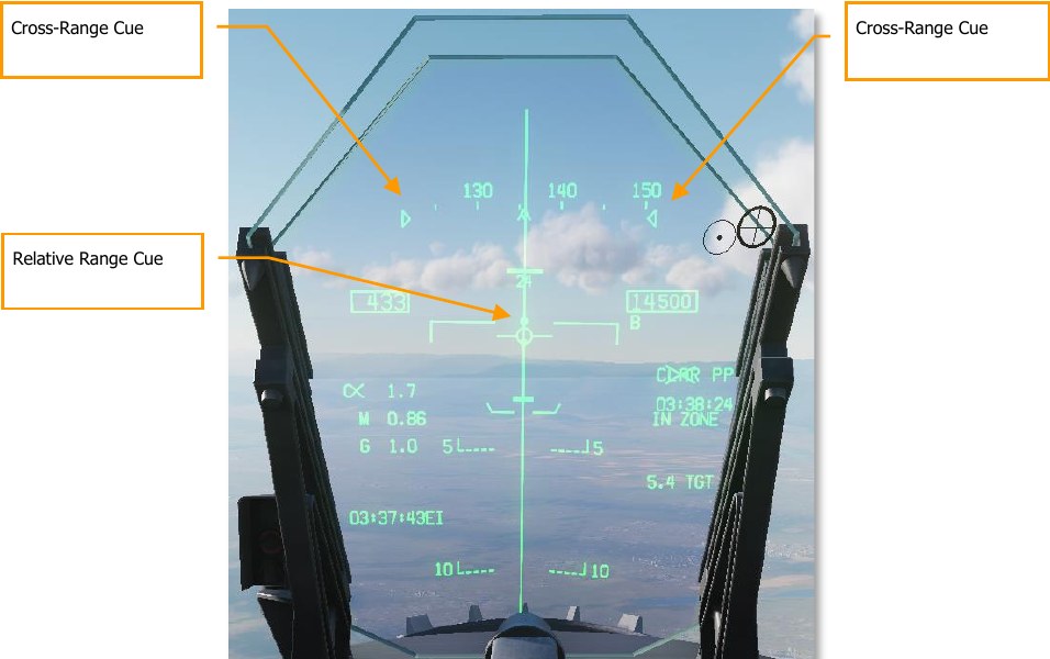
Relative Range Cue. Displays the aircraft’s current position between the min and max range cues, when inside the LAR.
Cross-Range Cue. Represents the lateral extent of the LAR at the aircraft’s position. Clamped to the edges of the heading tape at wider extents.
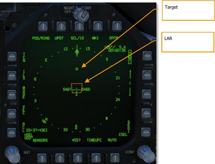
LAR. The launch acceptability region. Pre-planned LARs are displayed as orange and straight-line LARs as green. The straight-line LAR is only displayed when target steering error is less than 20°.
Using the GBU-24
To make a pre-planned attack using the GBU-24, first ensure that the target location is designated. You can designate a target using the HSI, the FLIR, or the A/G radar. Verify that the aircraft is in A/G master mode and MASTER ARM is on. Verify that the LTD/R is powered on if you will be lasing your own bomb.
- On the STORES format, box GB24.
- For a pre-planned attack, set the MODE to CLAR PP by pressing the MODE pushbutton. For a straight-line attack, set the MODE to CLAR SL.
- For a pre-planned attack, press the UFC pushbutton, then press the Option Select Button labeled CLAR, then the Option Select Button labeled HDG. Enter the attack heading (true heading) and press ENT on the UFC.
- On the STORES format, verify the laser code and fuzing are correct.
- Fly the aircraft into the LAR. The ASL will become solid, and the Weapon Release button will be hot. Press the Weapon Release button to release the weapon. If the LTD/R is powered on, it will automatically begin lasing prior to predicted impact time.
The GBU-24 can also be used for on-call attacks when another platform is lasing. On the STORES page, pressing the CLAR OVR pushbutton will inhibit normal release calculations and allow the bomb to be released immediately.
A strong crosswind can have an unanticipated effect on the LAR. In a crosswind, the aircraft must crab into the wind to maintain a straight ground track to the target. This points the bomb’s seeker head upwind. This forces the LAR to shift upwind, even though after release the bomb will drift downwind. In sufficiently strong crosswinds, flying the ASL may never result in the aircraft penetrating the LAR.
INS/GPS-Guided Weapons
The INS/GPS-guided weapons of our Hornet include both the Joint Direct Attack Munition (JDAM) and the Joint Stand-Off Weapon (JSOW). Both allow considerable standoff range when combined with high-altitude, high-speed launches. They offer excellent accuracy with launch-and-leave capability.
Joint Direct Attack Munition (JDAM)
Low-drag general-purpose bomb fixed with an attached JDAM guidance kit. Guidance is obtained by an onboard Inertial Navigation System (INS) aided by a Global Positioning System (GPS) processor. The JDAM guidance kit provides accurate guidance in all-weather conditions, day or night. JDAM is a programmable system that allows multiple weapons to be independently targeted prior to release. Targeting data are entered as lat/long/alt coordinates and are provided to the weapon by the pilot via the avionic interfaces. For the most accurate programming, precise hour:minute:second to hundredth of a second is available through the Mission Editor and F10 map by pressing LAlt + Y.
| DESIGNATION | BOMB | GUIDANCE KIT | RACK | STATIONS | FUZE OPTIONS |
|---|---|---|---|---|---|
| GBU- 31(V)1/B | Mk. 84 (2,000-lb warhead) | KMU-556/B | BRU-32 | 2, 3, 7, 8 | Nose: DSU-33A/B, DSU-33B/B Tail: FMU-152/B, FMU-139A/B |
| GBU- 31(V)2/B | Mk. 84 (2,000-lb warhead) | KMU-556/B | BRU-32 | 2, 3, 7, 8 | Nose: DSU-33A/B, DSU-33B/B Tail: FMU-152/B, FMU-139A/B |
| GBU- 31(V)3/B | BLU-109 (2,000-lb penetrator warhead) | 2, 3, 7, 8 | Tail: FMU-152/B, FMU-139A/B | ||
| GBU- 31(V)4/B | BLU-109 (2,000-lb penetrator warhead) | KMU-558/B | BRU-32 | 2, 3, 7, 8 | Tail: FMU-152/B, FMU-139A/B |
| GBU- 32(V)2/B | Mk. 83 (1,000-lb warhead) | KMU-559/B | BRU-32 | 2, 3, 7, 8 | Nose: DSU-33A/B, DSU-33B/B Tail: FMU-152/B, FMU-139A/B |
| GBU-38/B | Mk. 82 (500-lb warhead) | KMU-559/B | BRU-32 (×1), BRU-55 (×2) | 2, 3, 7, 8 | Nose: DSU-33A/B, DSU-33B/B Tail: FMU-152/B, FMU-139A/B |
EFUZ options: INST (instantaneous), DLY1 (delayed).
AGM-154 Joint Standoff Weapon (JSOW)
Glide weapon that allows much greater attack distances than the JDAM, but still uses INS/GPS navigation for great accuracy. As with JDAM, it can be targeted against preplanned (PP) targets or targets of opportunity (TOO) and is a 1,000 pound- class weapon with a launch range up to 15 nm at low altitude and 60 nm at high altitude.
| DESIGNATION | BOMB | RACK | STATIONS | FUZE OPTIONS |
|---|---|---|---|---|
| AGM-154A | BLU-97/B (combined effects bomb) | BRU-32 (×1), BRU- 55A/A (×2) | 2, 3, 7, 8 | Tail: FMU-152/B, FMU-139A/B |
| AGM-154C | BROACH (multi-stage penetrating) | BRU-32 (×1), BRU- 55A/A (×2) | 2, 3, 7, 8 | Tail: FMU-152/B, FMU-139A/B |
INS-GPS Weapon in TOO Mode
- Master Arm switch to ARM
- Master Mode switch to A/G
- Select JDAM or JSOW bomb from top of the SMS page
- Select TOO mode
- Allow weapons to align down to 7:30 for GOOD ALN QUAL
- Set EFUZ to INST
- Select JDAM/JSOW DSPLY
- Set QTY (quantity to drop)
- Designate desired target
- Align steering with target bearing and press weapon release button when IN RNG cue on HUD is displayed
INS-GPS Weapon in PP Mode
- Master Arm switch to ARM
- Master Mode switch to A/G
- Select JDAM or JSOW bomb from top of the SMS page
- Select PP mode
- Allow weapons to align down to 7:30 for GOOD ALN QUAL
- Set EFUZ to INST
- Select JDAM/JSOW DSPLY
- Set QTY (quantity to drop)
- Select MSN (pre-planned mission)
- Select PP mission (1 to 6)
- Select the TGT UFC and enter ELEV (elevation) and POSN (position coordinate) of the mission target
- Align steering with target bearing and press weapon release button when IN RNG cue on HUD is displayed
Weapon Selection
Upon initial weapon selection and timing is complete (after 2:30), all currently inventoried weapons of the same variant are placed into STBY (standby) status as indicated under their respective weapon acronyms. All weapons simultaneously begin alignment and will remain initialized if at least one weapon station of the same type is selected.
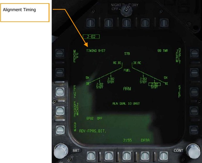
Deselecting JDAM/JSOW will likewise cause all weapons of the same type to spin down, requiring at least 2.5 minutes for warmup to complete again. Consideration should therefore be given to this warmup cycle when mission planning. The status of this alignment cycle is indicated on the STORES format and JDAM/JSOW displays as a TIMING cue which is initialized to 10:00 minutes and counts down. The TIMING cue is removed when the Time-to-Go (TTG) reaches 7:30 (alignment is GOOD after 2:30).
When a GPS weapon is initially selected, all stations of the same store type are simultaneously placed in STBY until the TIMING cue is removed, at which point the priority station will either remain in STBY or transition to RDY (ready), depending on A/G Ready status (i.e., warmup complete, designation exists and is valid). All additional stores of the same type will remain in STBY until selected (RDY cue), explicitly deselected, or indirectly deselected by the selection of a different weapon type or upon transition to A/A master mode.
JDAM JSOW Stores Format
As with other A/G stores, all GPS weapons including JSOW and JDAM may be selected in NAV or A/G master modes by boxing the applicable weapon acronym from weapon selection menu across the top row of push buttons from the STORES planform format.
JDAM and JSOW versions are listed as follows on the JDAM format page:
- J-109 = GBU-31(V)4/B
- J-84 = GBU-31(V)2/B
- J-83 = GBU-32(V)2/B
- J-82 = GBU-38 (needs BRU-55A/A)
- JSA = AGM-154A
- JSC = AGM-154C
Selection of any GPS weapon on the STORES format applies power to every inventoried GPS weapon of the same type. Power remains applied to the GPS weapons until deselected. A GPS variant is deselected only when the associated weapon select option is unboxed explicitly, or another weapon type is selected. When operational power is first applied, warm-up and transfer alignment begin. As soon as warmup is complete (2.5 minutes from initial power up), the weapon may be armed for release. Note that the alignment quality is not a prerequisite for release interlocks and achieving an alignment quality of GOOD may take as long as 10 minutes.
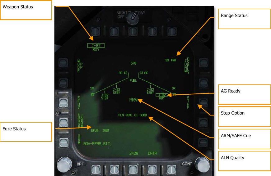
Weapon Station/Status. The priority station is boxed when selected and is the station which is currently accepting targeting data. The station status cue represents the status or health of the station.
- Priority Station. Selecting a PP# mission option (or TOO) assigns that mission (or TOO) to that specific station. Subsequently changing the priority station will load any previously selected mission for that station. For example, station 3 may be assigned to mission PP2 and station 9 may be assigned to mission PP1.
- Station Status Cue. Displayed below each station on the wing planform is the station status. When any single GPS weapon is selected, all stations with the same variant are automatically places into standby. Only the priority station is boxed, but a STBY status is displayed at each useable station unless overridden by a higher priority status (e.g., SFAIL or WFAIL). If the status of any weapon in the quantity changes, the status reflects the change, but the weapon remains in the quantity.
ALN QUAL. Indicates the priority station navigational state. This is the state of the weapon’s internal guidance alignment status. Weapon INS alignment quality takes time to improve. This cue consists of a numeric value from 01 (best) to 10 (worst) and a plain language cue of UNST, MARG or GOOD. All weapons initialize in the 10 UNST state.
- Time 10:00 to 9:15: ALN QUAL 10 to 7, UNST
- Time 9:15 to 8:30: ALN QUAL 6 to 3, MARG
- Time 8:30 to 7:40: ALN QUAL 2 to 0, GOOD
ARM/SAFE Cue. The status of the master arm logic is continuously displayed in 200% size letters as:
- SAFE. The weapon is disarmed
- ARM. The weapon is armed, but not necessarily RDY
- SIM. The weapon is disarmed, in Simulation (SIM) mode. When simulation mode is selected, SIM is displayed in this location in place of SAFE or ARM
STEP Option. Provided when the SMS determines that more than one weapon of the selected type is available for release and the quantity is greater than 1. Each successive depression of the STEP option causes the SMS to change the priority station indication to the next available station in the station priority sequence. If a release quantity of more than one is selected for a given conventional, laser-guided, or GPS-guided bomb, the SMS will automatically step to the next available priority station before releasing the next weapon in the salvo. The first weapon released in a quantity release is always from the station which is currently selected. The priority station the SMS chooses in quantity releases is prioritized based on loading priority to reduce to a minimum the lateral moments created by asymmetrical loads. For example, if a weapon is released from an outer wing pylon, the SMS will select the matching opposite pylon (if available) for the next station in the priority sequence.
Range Status. The Range Status cues refer to the weapon at the priority station:
- ## TMR. If the aircraft is outside the Launch Acceptability Region (LAR) and the target is within the forward hemisphere of the aircraft, this cue will read ## TMR indicating the time in seconds (99 max) until the aircraft is within the maximum range of the weapon at the current (no launch zone specified), or reference (LZ specified) altitude.
- IN RNG. If the aircraft is within the aerodynamic range of the weapon, but is not yet within the LAR, IN RNG will be displayed here. Generally speaking, and at least in terms of the current simulation, IN RNG will be transient, as IN ZONE will occur almost immediately following IN RNG.
- IN ZONE. This cue indicates the aircraft is within the LAR and the weapon should be released.
A/G Ready. When a weapon of any type other than the gun is selected, the corresponding A/G menu acronym will be boxed just as it is under the individual stations. The status for the weapon is also echoed here. Pressing a boxed weapon option will deselect that weapon and select no weapon. Likewise, selecting an unboxed weapon will select that weapon, and the SMS will automatically provide the selected station based on the priority sequencing algorithm.
Fuzing Status. The EFUZ or MFUZ fuze status due indicates the armed or safe status of the fuzes for the selected JDAM.
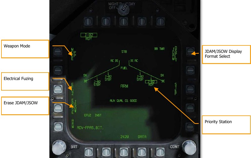
Weapon Mode. PB5 selects the GPS targeting mode for the priority station.
- Pre-Planned (PP). Instructs the priority weapon to execute the selected pre-planned mission, if valid.
- Target of Opportunity (TOO). Instructs the priority weapon to cue to the sensor-designated target, if any.
ERASE JDAM/JSOW. This option immediately clears all GPS weapons of the selected variant of all previously entered pre-planned (PP) mission data. JDAM/JSOW ERASE is boxed when selected and remains boxed for 5 seconds. JDAM/JSOW ERASE cannot be undone. If JSOW is the selected weapon, ERASE JSOW is displayed.
Electrical Fuzing. Located at pushbutton 3 when an electrical fuze is mounted to the selected JDAM or JSOW. Upon selection, pushbutton 5 displays OFF, pushbutton 3 displays INST, and pushbutton 2 displays VT1 or DLY1 for FMU-139 fuze.
- If DSU-33 is present = VT1
- If DSU-33 not present = DLY1
Priority Station. The currently selected priority station. If A/G Ready is false (e.g., weapon is warming up, Master Arm false, or no valid target exists, or the label is X’d out). This is shown as STA (station number). For example, STA7. To the right is the status of the selected station and can be:
- RDY, ready
- RDY-D, ready but degraded
- FAIL, failed
- TEST, in BIT
- XFER, transferring target data in MUMI page
- STBY, standby
JDAM/JSOW DSPLY Format Select. This option, at pushbutton invokes the JDAM/JSOW Format for mission data entry.
Upon selecting the JDAM/JSOW Display Format at pushbutton 11, the following page functions and information is available:
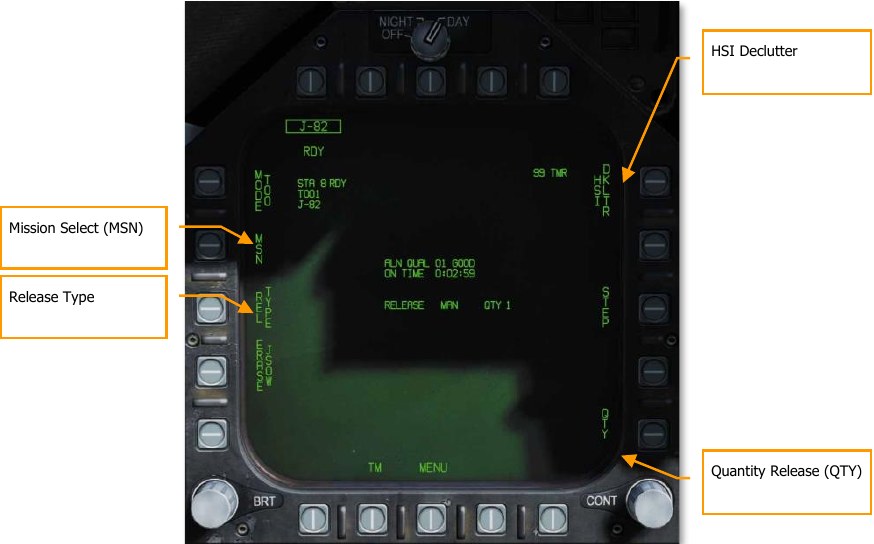
HSI Declutter. When boxed, this option removes any weapon specific HSI symbology which lies outside of IRLAR circle (see HSI Symbology, below). Later in early access.
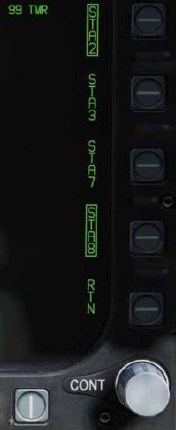
Quantity Release (QTY). Pressing this option at pushbutton 15 displays stations loaded with the JDAM or JSOW type as selected from pushbutton 11 to 14. Only stations loaded with JDAM or JSOW are displayed.
- Pushbutton 11 = STA2
- Pushbutton 12 = STA3
- Pushbutton 13 = STA7
- Pushbutton 14 = STA8
Selecting a station boxes it and adds it to the QTY value. RTN exits the quantity release selection. 4 is the maximum allowable quantity. Each selected station will be cued to release on the selected target in PP or TOO mode.
Release Type. This cue lists the selected release mode for the selected weapon: MAN (Manual), AUTO LOFT, and FD (Flight Director). Manual is mode is implemented at this time in the early access. Upon selection of the release mode, the selection displayed to the left of the release quantity.
Mission Select (MSN). Located at pushbutton 4, selecting the mission displays the mission format page for either PP or TOO modes.
Mission Options. This page allows the player to create Target Data Sets (TDS) for the selected JDAM against the selected target. The Mission Data (MSN) format is accessed by pressing the MSN option at pushbutton 4. The Mission Data format is used to select and program one of the 6 available PP missions. A mission is selected by depressing one of the PP# options at PB6-PB11. One of the various UFC options along the lower right side of the format is then selected to begin program data entry. Note that program data may be pre-programmed in the Mission Editor. If TOO mode is selected, mission data for the selected Target (TGT) is displayed.
Pre-Planned (PP) Missions SMS Format
Pre-Planned allows entry of specific target coordinates. This option is what is referred to as a Pre-planned (PP) Mission. In the current early access, this is done through coordinate entry via the UFC. There is a total of six PP missions available for programming and each weapon station may be assigned to any one of these missions. The MC then determines the maximum range of the weapon at the current altitude and airspeed. A PP mission is selected by boxing one of the 6 available PP mission pushbuttons located along the top of the MSN display.
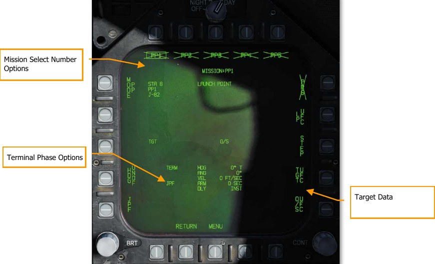
Mission Select Number Options. Pre-Planned (PP) mission targets are set either in the Mission Editor or via the UFC and up to six can be selected from pushbutton 6 to 11. The selected PP mission is boxed. If a PP mission does not contain valid coordinates and elevation, the PP(x) legend is X’d out. PP missions are not displayed when in TOO mode.
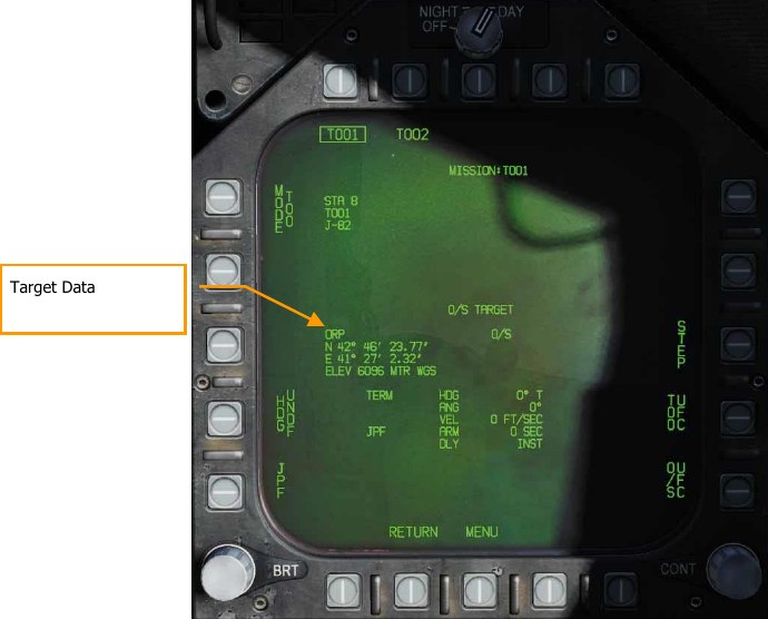
Target Data. The target coordinates and elevation for the selected PP mission may be specified via the UFC, and if valid, are displayed here. They may also be set as a preplanned target created in the
Mission Editor. If the target is an OAP (an offset was specified), the TGT label becomes OAP, and the OAP relative bearing and distance are displayed to the right of the OAP data area. The latitude and longitude of the target are displayed in this data block, as well as target elevation.
Target Data Entry. Upon selecting the Target Data UFC Entry pushbutton 14, you will use the UFC to enter the target coordinate and elevation for the selected PP mission.
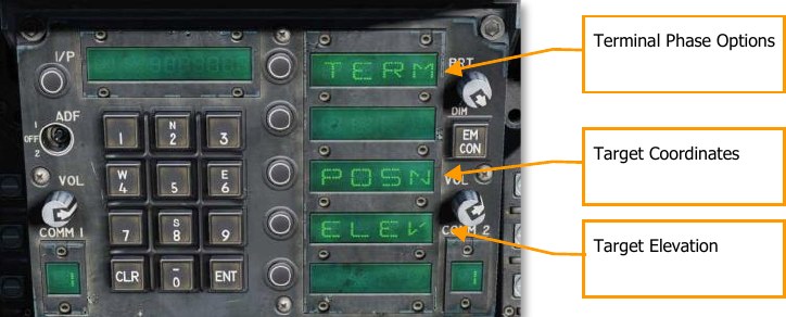
POSN is the lat / long coordinate of the target. This is entered as longitude and longitude in degrees, minutes, and seconds.
ELEV can be entered in FEET or MTRS (meters). Valid range for FEET is -328 to 32808 and MTRS is - 100 to 10000. We will skip MSL or WGS selection as pictured below. Once a valid elevation and target coordinate have been entered and saved, the selected PP mission will no longer have an “X” through it and the TGT (target) information on the MSN screen will be complete.
Terminal Phase Options are entered as the weapon impact angle, weapon impact heading, and weapon impact velocity. Selecting TERM displays three options on the UFC for:
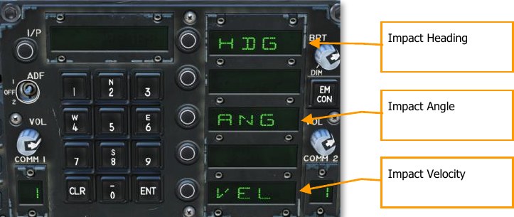
- HDG. Heading of weapon at time of impact. Valid range if from 0° to 359°.
- ANG. This is the impact angle of the weapon. Valid range is 0° to 90°.
- VEL. Velocity at impact. Valid range is 100 to 26800 feet per second.
Target of Opportunity (TOO) Missions
TOO initializes the selected weapon with the current ground target. Currently, this is set as the designated waypoint (WPDSG). Any subsequent weapons in the same salvo (using QTY) which are also using TOO will receive the same coordinates. The primary difference from PP mode is the ability to set a target point (TGT) using a waypoint or sensor.
Upon selecting MSN at pushbutton 4, the TOO mission page will display the elevation and coordinates of the target. At this stage in the early access, this will be a designated waypoint. As with PP mode, the target elevation and coordinate are displayed on the SMS TOO mission format.
JDAM and JSOW HSI Format
When a TOO target or PP mission has been created with a valid elevation and coordinate, the target/mission location is displayed on the HSI, along with the minimum range, in range launch acceptable region (LAR), and predictive maximum range bar. There are provided to better visualize target/mission location regarding weapon range.
JDAM/JSOW Target. This is a solid triangle symbol at the location of the PP target location, or a solid diamond if a TOO target location. The symbol shows the last selected PP or TOO mission.
Minimum Range. This is a circle that is centered on the target and indicates the minimum acceptable launch radius of the selected JDAM or JSOW. This cue is not displayed when the aircraft is within the IZLAR.
In Range LAR (IRLAR). This larger circle is also centered on the target and represents the range at which the selected JDAM or JSOW can be launched under current flight conditions (heading, altitude, and airspeed) and provide a minimum impact angle of 35° and a minimum impact velocity of 300 feet per second. This cue is removed when the aircraft is within the IRLAR.
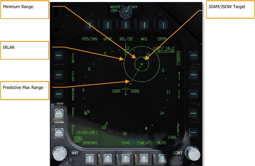
Predictive Max Range. This dashed line indicates the absolute maximum launch range to the target, not accounting for impact angle and speed. This will always be greater than the IRLAR. The line will run from the target and through the ownship. At the end of the dashed line is a bar. This bar should always be at 60 nm which is the best-case maximum range for a JSOW.
JDAM and JSOW Manual Mode HUD
With a TOO target or PP mission created, steering commands, distance, and release zone indications are provided on the HUD when in manual mode. For manual mode, there is no azimuth steering line or release cue as normal for AUTO modes. Instead, target/mission bearing is indicated and an in range (IN RNG) cue is provide when the weapon is between minimum and maximum range.
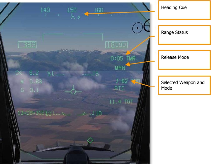
Heading Cue. This cue on the heading tape provides steering direction to the IZLAR. If a release quantity of more than 1 is selected, this cue is not displayed and the waypoint or TACAN cue is displayed instead.
Range Status. The Time to Maximum Range (TMR) is visible when the aircraft is within 10 minutes of reaching the IZLAR. It will then start at 9:59 and count down as range closes. Once the aircraft is within the IRLAR, the cue changes from TMR to IN RNG. The IN RNG will flash if the aircraft is within 5 seconds of flying outside the INLAR or inside the minimum range zone. If the aircraft is inside the IZLAR zone, then the cue changes to IN ZONE.
Release Mode. Shown as MANUAL when in manual mode. If not in MAN, AUTO LFT is displayed.
Selected Weapon and Mode. Displays the name of the selected weapon type (J-83, J-84, J-109, or 154A) and either TOO or PP based on mode selection.
Air-to-Ground Gun and Rockets
Two modes for the A/G gun and rockets are available from the A/G Stores page: CCIP and MAN. These can be enabled by selecting the weapon from the A/G SMS page and then selecting the desired delivery mode. They feature either a “point and shoot” CCIP reticle or a manually adjusted manual sight based on a manual mil setting. Both the A/G Gun and Rockets are very similar in their programming, HUD, and delivery modes.
How to Use A/G Guns
- Master Mode switch to A/G
- Select/box GUN on the A/G SMS page with no other weapon selected
- Select Mode as CCIP
- Fly to place the pipper in the center of the Reticle over the target and hold down the trigger when the IN RNG cue appears on the HUD
How to Use Rockets
- Master Mode switch to A/G
- Select rockets at the top of the A/G SMS page
- Select Mode as CCIP Mode
- Fly to place the pipper in the center of the Reticle over the target and hold down the trigger when the IN RNG cue appears on the HUD
A/G Gun SMS Page
- A/G Gun Option. The A/G gun is selected by pressing the GUN Option Select Button on the A/G SMS page. If another weapon is selected, the gun will operate in Hot Gun mode (fixed 2,000 ft gun cross). When selected, the GUN legend is boxed and an RDY (Ready) indication is displayed to the left of the box.
- Mode Selection. Separate buttons are available for CCIP and MAN modes. Selecting a mode boxes the legend.
- Gun Ammunition Type. Gun ammunition can be selected between M50 and PGU-28B 20mm rounds. The selected gun round type is boxed.
- Gun Fire Rate. HI (High) and LO (Low) gun fire rates can be selected with the selection being boxed.
- UFC. When the Mode is set to MAN (Manual), the UFC Option Select Button is displayed. Pressing this button boxes the legend and allows the pilot to manually enter the gun reticle depression on the UFC. The value can range from 0 to 270 mils. Once complete, the ENTER button on the UFC is pressed to save the value. Note that this value is not saved to a program.
- Reticle Setting. Next to the RTCL is the entered reticle setting in mils.
- Gun Rounds Remaining. At the top of the wingform, the number of gun round remaining is displayed, with a full load being 578 rounds.
Rockets SMS Page
- Rocket Selection. The top row of options is used to select the desired A/G weapon. One option is provided for each displayed weapon type (maximum 5). An abbreviation of the selected weapon type is displayed below the push tile. When a weapon is selected, the abbreviation is boxed. Pressing the button again will unselect the weapon. If the A/G weapon is in a release condition, “RDY” is displayed below the weapon box. Otherwise, an “X” is displayed through the weapon box.
- Wingform Indication. When a rocket pod is selected, its indication on the Wingform will boxed. Next to the rocket type abbreviation, the number of remaining rockets in the pod on the station is indicated. Successive presses of the STEP button will cycle the selected weapon station of rockets of the same type.
- Mode Selection. Separate buttons are available for CCIP and MAN modes. Selecting a mode boxes the legend.
-
Firing Mode. Options for SGL (single) and SAL (salvo) are displayed when more than one rocket pod of the same type is loaded on the aircraft. When SGL is selected, one rocket will be launched with each press of the Weapon Release Button. When SAL is selected, two rockets will be launched with each press of the Weapon Release Button, from different rocket pods.
When SAL is selected, the weapon STEP option is not available.
-
MTR (Motor) Type. Most rockets can have one of two motor types: M4 or M66. Presses of the MTR Option Select Button cycles between the two types with the selected being boxed.
-
UFC. When the Mode is set to MAN (Manual), the UFC Option Select Button is displayed. Pressing this button boxes the legend and allows the pilot to manually enter the rocket reticle depression on the UFC. The value can range from 0 to 270 mils. Once complete, the ENTER button on the UFC is pressed to save the value.
-
Reticle Setting. Next to the RTCL is the entered reticle setting in mils.
A/G Gun and Rocket HUD
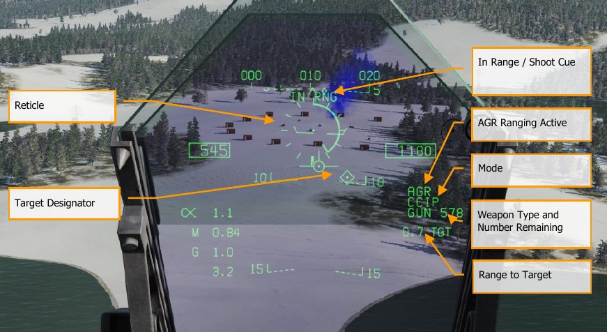
Reticle. This Reticle consists of tic marks in 50-mil diameter circle with a pipper in the center. When in CCIP mode, the Reticle indicates the calculated impact point of the gun rounds/rocket. When in MAN mode, the reticle is adjusted based on the depressible mils setting from the SMS page/UFC.
When in CCIP mode, an analog range bar is inscribed within the reticle. Slant range is provided by the radar via Air to Ground Ranging (AGR) and barometric altitude. Each tic mark on the reticle represents 1,000 feet of slant range and can indicate ranges from 0 to 23,000 feet. The bar will rotate clockwise to indicate increasing range and rotate counterclockwise to indicate decreasing range.
In Range / Shoot Cue. When in CCIP mode and the gun/rocket is within maximum slant range of the pipper’s aim point, the “IN RNG” cue is provided. If, however, there is a designated ground target, the “SHOOT” cue will be displayed if the gun/rocket is within range of the target.
Mode. The selected delivery mode for the gun/rocket is indicated as either CCIP or MAN based on the SMS page program setting.
AGR Ranging Active. When in CCIP mode and the radar is using AGR to determine range, the RDR indication is displayed. (Coming later in Open Beta)
Weapon Type and Number Remaining. The selected weapon name and the number of remaining rounds/rockets are displayed and updated as weapons are expended. This will display either GUN or RKT (rockets).
Range to Target. When a target has been designated and in CCIP mode is enabled, the range to the target is displayed in miles.
Target Designator. When the TDC is assigned to the HUD, the TD is displayed as a diamond within the HUD field of view with a pipper in the center. The TDC can then slew the TD within the HUD field of view.
When in MAN mode, true airspeed is displayed below the calibrated airspeed box.
Pressing the Cage/Uncage Button will fix the CCIP Reticle to 5,000 feet slant range.
Note
In the Mission Editor, there is an Aircraft Properties tab in the Aircraft/Payload menu. This can be used to set rocket pods on the inboard and outboard stations to ripple or single release.
AGM-65 Maverick
The Hornet can carry two versions of the AGM-65 Maverick air-to-ground missile: a laser guided version (AGM-65E) and the infrared guided AGM-65F. These missiles are carried on the LAU- 117A(V)2/A single rail launcher, which is attached directly to the BRU-32/A racks on wing stations 2, 3, 7, and 8. The Hornet does not support multiple carriage of AGM-65s on a single station.
- AGM-65E Laser Maverick: This is a 641-pound missile containing a laser-guidance system and solid fuel rocket motor. The guidance system automatically locks-on and tracks targets being illuminated by a properly coded laser illuminator (from a targeting pod or JTAC). For this example, we will use JTAC laser designation.
- AGM-65F IR Maverick: This is a 675-pound missile containing an infrared detector system and solid fuel rocket motor. The missiles provide infrared raster video to allow lock-on and tracking of targets which provide sufficient temperature contrast.
These Mavericks are automatically displayed on the Stores Management System page when a Maverick weapon is selected, and the SMS is set to a Maverick weapon station. The Maverick formats can also be selected through the TAC MENU, which contains an option (MAV for the AGM-65E or MAVF for the AGM-65F) when a Maverick weapon station is selected.
How to Employ the AGM-65E
- Master Arm to ARM and Master Mode switch to A/G
- Select MAV from the Stores TAC page
- Contact the JTAC radio and input directed laser code
- Fly to place target within 40 degrees off nose and press Cage/Uncage button C to scan for laser designation
- Press and hold the Weapon Release button RAlt + Space to launch the missile when laser designation is locked and within 8 nautical miles
AGM-65E Laser-Maverick on SMS Page
When an AGM-65E is loaded on the aircraft, its MAV code is displayed beneath the station is loaded on. The selected station for launch has the MAV indication boxed. Selection of the Maverick station can be cycled with the STEP option on pushbutton 13. Beneath each station is the four-digit laser- code. This code can be changed by pressing PB 14, labeled “UFC.”
MAV is listed below one of the top pushbuttons (6 to 10) and is boxed when selected. It will be crossed-out when the Maverick has not reached launch criteria.
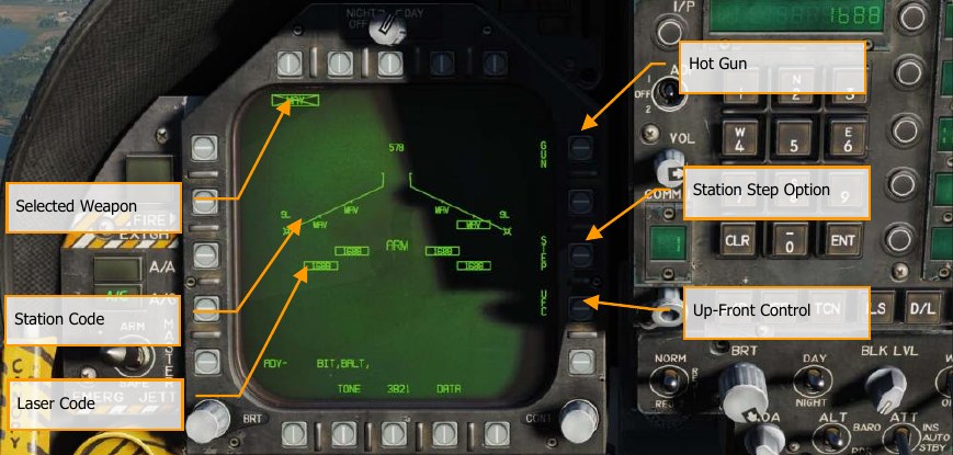
Up-Front Control. This option is selected to enable the Up-Front Control for entry of the laser code. Separate laser codes may be entered for each Laser Maverick on board, and do not have to be the same as the laser code for the Laser Spot Tracker or FLIR LTD/R.
Station Step Option. This option is provided when the SMS determines that weapons of the selected type are available for release from more than one weapon station. Each successive selection of the STEP option causes the SMS to change the priority station indication to the next available station in the normal station priority sequence which contains the selected weapon. The station priority sequence for the Laser Maverick is 8, 2, 7, 3
Laser Code. The entered code of the selected AGM-65E station.
Station Code. Station loaded with AGM-65E laser Maverick with MAV code.
Selected Weapon. Below pushbuttons 6 through 10 are listed the weapons detected as loaded. AGM-65E appears as MAV. The selected weapon for employment will have its code boxed. If the weapon is not in launch constraints, the code will be X’d through. Pressing the MAV will display the AGM-65E weapon format page.
AGM-65E Laser-Maverick Format Page, Unlocked
Upon selecting MAV from the SMS page, the AGM-65E Laser Maverick symbology is displayed on the DDI. The Laser Maverick format is shown below.
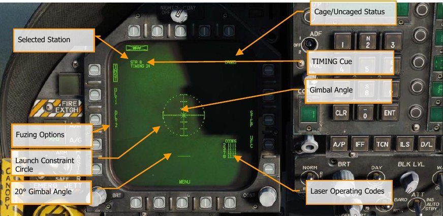
Selected Station. The Laser Maverick can be carried on stations 2, 3, 7, and 8. The weapon station selected by the SMS is indicated beneath the weapon selection status. The priority sequence is 8, 2, 7, 3.
TIMING Cue. When the Laser Maverick weapon is selected, the SMS applies power (AGM-65 Select signal) to all LAU-117A(V)2/A launchers attached to Laser Mavericks and provides a timing signal to the MC for display on the Maverick format. To ensure that the Laser Maverick is ready for launch, the SMS sends a 30 second countdown timer to the MC, which is displayed as an advisory cue, TIMING ##. The time ## decrements from 30 seconds to allow for worst-case gyro spin-up time and is removed at 0 seconds.
Fuzing Options. Three mutually exclusive fuzing options, instantaneous (INST) and two delay (DLL1, DLL2) options, are selectable for Laser Maverick electrical fuzing control. The selected fuzing is provided to the SMS for electrical fuse control via the AN/AWW-4(V) Fuse Function Control Set.
Launch Constraint Circle. The dotted launch constraint circle is part of the Maverick video. The radius of the circle is 15°. The horizontal tick marks represent 5° in elevation.
Gimbal Angle. The Maverick gimbal angle with respect to missile boresight is indicated by the “X” symbol which is part of the Maverick video. The “X” changes to a solid square symbol to indicate Maverick lock-on.
20° Gimbal Angle. The 20° gimbal angle position is indicated by the short horizontal line which is part of the Maverick video.
Laser Operating Codes. The current laser operating codes (entered via the UFC) are displayed for each Laser Maverick on board.
Caged/Uncaged Status. The caged/uncaged status of the weapon is continuously provided on the Maverick format. when the weapon is initially selected with no existing designation, CAGED is displayed. When an uncage signal is commanded to the missile (by depression of the uncage switch, action slewing of the TDC, moving the Sensor Control switch to the Laser Maverick format to command track, or by making a designation), UNCAGED is provided on the format.
AGM-65E Laser-Maverick Format Page, Locked
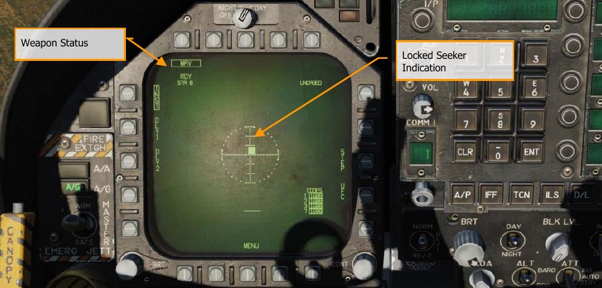
Weapon Status. An indication of weapon selection status is provided which is identical to that provided on the Stores format. when an A/G release ready condition exists, RDY is displayed beneath the weapon selection box. Otherwise, an “X” is displayed through the IR Maverick acronym (IMAV). If the weapon selection option is selected as shown below, the IR Maverick is deselected, and the IR Maverick format automatically reverts to the Stores format.
Locked Seeker Indication. When the laser Maverick achieves a positive track on the laser designation, the Gimbal Angle “X” changes to a solid square and still indicates the weapon seeker angle.
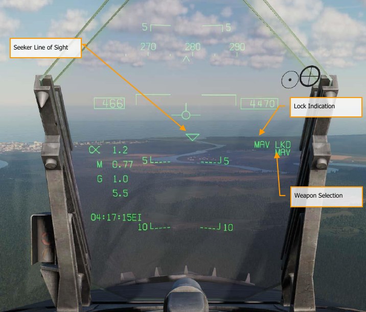
Seeker Line of Sight. This triangle symbol is centered in the HUD when the AGM-65E is selected as the active weapon. Upon seeker uncage, the symbol will perform a raster scan pattern across the field of view of the HUD in search of the laser designation matching the selected laser Maverick station. Upon detection and lock, the symbol is locked to the designated target and provides a line- of-sight reference.
Locked Seeker Indication. When the laser Maverick achieves a positive track on the laser designation, a MAV LKD (Maverick Locked) indication is displayed on the HUD. Weapon Selection. When an AGM-65E is selected, MAV is displayed on the HUD.
AGM-65E Format and Setting Laser Codes
From the laser Maverick format page, it is possible to enter laser codes for the Laser Mavericks, the Laser Spot Tracker, and the Laser Target Designator/Ranger using the UFC option. The laser codes are displayed on the wingform below the weapon wingform. when “UFC” is selected from the Stores format, all of the laser codes are boxed, and a single code may be entered for all laser stations using the UFC scratchpad, or the selected station may be cycled through the laser stations using the UFC option on the display (Sequence = all stations, 2, 3, 4, 6, 7, 8, all stations, 2, 3, etc.).
Depression of “ENTER” on the UFC enters a valid laser code if one was in the scratchpad and boxes the laser code(s) for the next laser station(s) in the sequence.
From the Laser Maverick format, it is possible to enter laser codes for all four Laser Mavericks using the UFC option. The laser codes can be displayed in a list on the right side of the format, with each Laser Maverick station and its associated code. When “UFC” is selected from the Laser Maverick format, all of the laser codes are boxed, and a single code can be entered for all laser stations using the UFC scratchpad, or the selected station can be cycled through the Laser Maverick stations using the UFC option on the display. Depression of “ENTER” on the UFC will enter a valid laser code if one was in the scratchpad and will box the laser code(s) for the next laser station(s) in the sequence.
How to Launch an AGM-65E
At aircraft start-up the SMS applies power to all Laser Maverick weapon stations. When the Laser Maverick is selected in A/G master mode, the SMS automatically selects the first available weapon in the station priority sequence. (The priority station sequence is 8, 2, 7, 3). At the same time the SMS commands gyro spin-up of all available Laser Maverick missiles. After a 5-second delay, the SMS provides the code data to all Laser Mavericks aboard by simultaneously selecting each Laser Maverick station and applying the code signals to the weapon. When a designation does not exist, the selected weapon is initially caged, and the caged status is indicated at the upper right corner of the display. The priority station selected, and the Laser Maverick launcher timing indication are displayed in the upper left corner of the display. When time-out is complete (after 30 seconds), the” TIMING ##” indication disappears.
When the Laser Maverick is placed into the scan mode by assigning the TDC to the Laser Maverick and depressing and releasing the TDC or uncaging the missile C. The SMS then provides both the uncage and slew enable commands to the selected weapon. While the TDC is depressed, forces may be applied to the TDC to adjust the azimuth and/or elevation angle at which the Laser Maverick is scanning. When the Laser Maverick is uncaged and the cage/uncage switch on the throttle is depressed, the SMS applies the uncage command to the Maverick launcher which results in caging the selected weapon. The weapon must then have the slew or slave command applied to enable scan or slave mode, and subsequent lock-on.
The HUD format indicating a Laser Maverick selected in A/G mode is shown above. This format includes the triangle symbol which indicates the Maverick LOS. The symbol sweeps back and forth across the HUD when the Maverick is scanning and is limited at the HUD FOV limits and flashed when the Maverick LOS exceeds these limits. A/G ready is indicated on the HUD by the absence of the “X” through the MAV acronym.
The Laser Maverick automatically locks onto a target illuminated with a correctly coded laser from scan and slew modes. If the missile is caged at boresight, the gimbal angle “X” will flash indicating that the seeker senses correctly coded laser energy. The TDC must be depressed, uncage signal applied, sensor control switch moved, or a target designated to lock on (these commands slew, which allows lock-on). The gimbal angle symbol on the Laser Maverick format is replaced by a solid square, as shown above, to indicate lock-on. Also, MAV LKD will be displayed on the right side of the HUD. The aircraft is maneuvered to satisfy the launch constraint and in-range criteria and the weapon release button is depressed for launch of the Maverick.
AGM-65F Infrared-Guided Maverick on SMS Page
How to Employ the AGM-65F
- Master Arm to ARM and Master Mode switch to A/G
- Select MAVF from the SMS page
- Set TDC control to the Maverick page
- Fly to place the triangle on the HUD near the target location
- Slew the crosshairs over the target on the Maverick display and release the TDC switch to lock the target.
- Press the weapon release button or RAlt + Space to launch the missile.
When an AGM-65F is loaded on the aircraft, its MAV code is displayed beneath the station is loaded on. The selected station from which to launch the laser-Maverick has the MAVF indication boxed. Selection of the Maverick station can be cycled with the STEP option on pushbutton 13. Beneath each station is the four-digit laser-code that can be edited with the UFC option on pushbutton 14. MAVF is listed below one of the top pushbuttons (6 to 10) and is boxed when selected. It will be crossed-out when the Maverick has not reached launch criteria.
When an AGM-65F is loaded on the aircraft, it is listed below each loaded station on the wingform as MAVF. The selected station is boxed, but the selected station can be cycles with consecutive presses of STEP on pushbutton 13.
MAVF is listed below one of the top pushbuttons (6 to 10) and is boxed when selected. It will be crossed-out when the Maverick has not been tracked to a target.
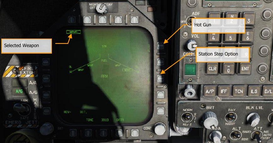
Station Step Option. This option is provided when the SMS determines that weapons of the selected type are available for release from more than one weapon station. Each successive selection of the STEP option causes the SMS to change the priority station indication to the next available station in the normal station priority sequence which contains the selected weapon. The station priority sequence for the infrared Maverick is 8, 2, 7, 3
Selected Weapon. Below pushbuttons 6 through 10 are listed the weapons detected as loaded. AGM-65F appears as MAVF. If the weapon is not locked to a target, MAVF will be X’d through. Pressing the MAVF will display the AGM-65F weapon format page.
AGM-65F Infrared Maverick Format Page, TIMING
If a mission is started on the ground or on the carrier, the AGM-65F will first need to spin up its gyro and cool down its seeker upon takeoff and selection of MAVF from the SMS. Upon which, the TIMING cue will decrement from 3-minutes. During this period, no video is displayed to the MAVF format page. Once the 3-minutes period has elapsed, Maverick symbology is displayed on the DDI.
If you were to land and re-arm with AGM-65F Mavericks, this timing period would need to be repeated.
If a mission starts airborne, the timing will have already been accomplished. Elements of the MAVF page while in TIMING mode include:
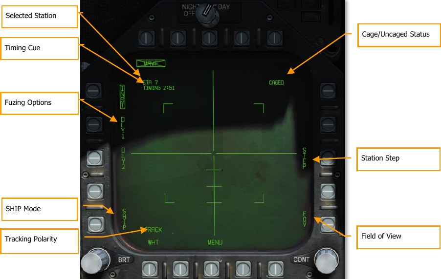
Station Select. The IR Maverick can be carried on stations 2, 3, 7 and 8. The weapon station selected by the SMS is indicated beneath the weapon selection status. The priority sequence is 8, 2, 7 then 3.
TIMING Cue. When the infrared Maverick weapon is selected, the SMS applies power (AGM-65 Select signal) to all LAU-117A(V)2/A launchers attached to Laser Mavericks and provides a timing signal to the MC for display on the Maverick format. To ensure that the Laser Maverick is ready for launch, the SMS sends a 3-minute countdown timer to the MC, which is displayed as an advisory cue, “TIMING ##”. The time ## decrements from 180 seconds to allow for worst-case gyro spin-up time and is removed at 0 seconds.
Fuzing Options. Three mutually exclusive fuzing options, instantaneous (INST) and two delay (DLL1, DLL2) options, are selectable for Laser Maverick electrical fuzing control. The selected fuzing is provided to the SMS for electrical fuse control via the AN/AWW-4(V) Fuse Function Control Set.
Ship Track. Selection of this option will set the Maverick seeker guidance and control to optimize for a ship target and offset the impact point to the ship’s waterline. The Maverick horizontal tracking gate will widen to twice the length of the vertical tracking gate while the Maverick is in “SHIP TRACK” mode and is not in the TRACK mode.
Tracking Polarity. Track polarity is indicated by the label displayed at this option. While the missile not in Track mode, either “TRACK WHT”, or “TRACK BLK” may be selected. The Maverick composite video is only displayed in White Hot mode. Therefore, when the display indicates “TRACK WHT”, the missile will track on the hot (white) target when it is commanded to track. When the format indicates “TRACKL BLK”, the missile will track on the cold (black) targets. The missile will reflect the selected tracking polarity by displaying the Maverick crosshairs and the pointing cross in either back for “TRACK BLK” or white for “TRACK WHT”. The tracking polarity will initially be set to “TRACK WHT” (hot on cold). The TRACK option will not be displayed Forced Correlate track is selected.
Caged/Uncaged Status. The caged/uncaged status of the weapon is continuously provided on the Maverick format. when the weapon is initially selected with no existing designation, CAGED is displayed. When an uncage signal is commanded to the missile by depression of the uncage switch, UNCAGED is provided on the format.
Station Step (STEP). This option is provided when the SMS determines that weapons of the selected type are available for release from more than one weapon station. Each successive selection of the STEP option causes the SMS to change the priority station indication to the next available station in the normal station priority sequence which contains the selected weapon. The station priority sequence for the Laser Maverick is 8, 2, 7, 3.
Field of View. The IR Maverick will place four corner brackets within the wide FOV indicating what area will be encompassed in narrow FOV. The corner brackets are not displayed in narrow FOV. The IR Maverick will initialize to wide FOV. While the IR Maverick is not in Track mode, the FOV (FOV) options can be toggled via two methods. The FOV can be changes by selecting FOV option on the Maverick display page, or by the throttle outboard switch (HARM Sequence/FLIR FOV/Raid).
AGM-65F Infrared Maverick Format Page
Once the TIMING has been completed after 3-minutes, infrared video is displayed on the MAVF format page. To slew the MAVF seeker, the TDC must be assigned to the DDI that is assigned the
Maverick format page. To do so, move the Sensor Control Switch in the direction of the DDI assigned to the Maverick. Upon TDC assignment, the TDC-control diamond is displayed in the top right corner of the Maverick format.
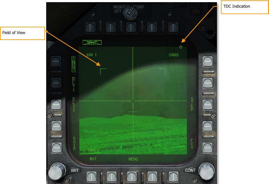
TDC Indication. This diamond-shaped symbol appears in the upper right corner of the display whenever the TDC is assigned to the IR Maverick.
Field of View. The IR Maverick will place four corner brackets within the wide FOV indicating what area will be encompassed in narrow FOV. The corner brackets are not displayed in narrow FOV. The IR Maverick will initialize to wide FOV. While the IR Maverick is not in Track mode, the FOV (FOV) options can be toggled via two methods. The FOV can be changes by selecting FOV option on the Maverick display page, or by the throttle outboard switch (HARM Sequence/FLIR FOV/Raid). Press C.
AGM-65F Infrared Maverick Targeting
With the TDC assigned to the Maverick format page, the seeker may be slewed within the gimbal limits of the seeker. This can be done in one of two ways based on the selection of the Options / Hornet / Special Tab / Hornet: Realistic TDC Slew option.
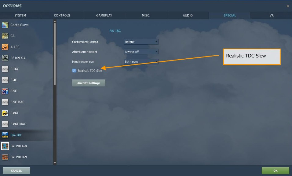
- Realistic TDC Slew Option Enabled. To slew the seeker with the TDC, the TDC must be depressed Enter while at the same time slewing the seeker ,, ., /, and ;. Slew the crosshairs in the center of the display over the desired target and release the TDC switch depress to command a lock of the target. If successful, the crosshairs will collapse around the target and track it in stabilized mode. If unsuccessful, the seeker will not lock and go to break lock mode in which the crosshairs expand.
- Realistic TDC Slew Option Disabled. Some controllers may have difficulty recognizing multiple inputs at once. If you have trouble with the realistic option, please disable it and try this. Instead of requiring the TDC to be depressed while slewing the seeker, you can instead simply slew the seeker with ,, ., /, and ; with no TDC depress. Slew the center of the crosshairs over the desired target and cease slew movement. Wait up to two seconds to allow the seeker to lock on to the target. If successful, the crosshairs will collapse around the target. If unsuccessful, the crosshairs will expand out.
When slewing the seeker, the center of the vertical horizontal bars (crosshair) marks the location where the seeker will attempt to lock a target. When slewed off boresight, the pointing cross provides a reference of the seeker line of sight offset from boresight.
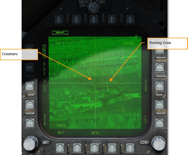
Pointing Cross. The seeker position will be indicated by a small pointing cross. The pointing cross position relative to the large crosshairs will indicate the seeker position. Relative to missile boresight the tick marks along the vertical crosshair are spaced by 5°, thereby indicating the depression angle and the scale. When the IR Maverick is in track and either the target is not within the launch constraint window or the tracking performance is poor, the small pointing cross will flash. A steady pointing cross will indicate a good lock.
Slave Maverick to Target (TG)
In addition to manually slewing the seeker to locate and lock onto a target, the seeker may also be slaved to a target (TGT). This could be a waypoint designated target (WPDSG) or a target created with a sensor. With a TGT created, the Maverick seeker will slew to the target location. Once there, press the Undesignate S button to uncage the seeker and allow manual slew.
On the HUD, we have indications for the Maverick line of sight and the status of the seeker tracking.
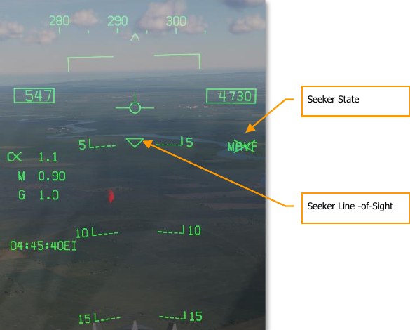
Seeker State. With the AGM-65F selected, MAVF is displayed along the right side of the HUD with an X through it, indicating it is not in track mode.
Seeker Line-of-Sight. This triangle on the HUD indicates the seeker line-of-sight through the HUD. This can be a useful cue to visually slew the seeker to the target location.
AGM-65F Infrared Maverick Tracking
Once the Maverick seeker has locked to a target, new information is presented on the Maverick format and the HUD.
On the HUD, the triangle line-of-sight indicator will be stabilized to the target location and the MAVF indication will no longer have an X through it.
On the Maverick format page, RDY will be displayed below the MAVF weapon indication, and the crosshairs collapsed on the target.
Pressing the weapon release button or RAlt + Space will launch the missile. Once launched, the video will cease from the missile just fired and move to the next Maverick in priority if one is loaded.
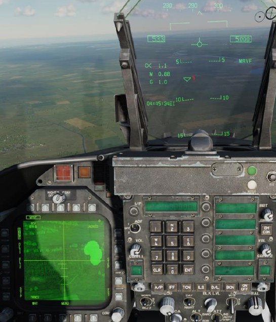
AGM-88 HARM
The AGM-88C High-Speed Anti-Radiation Missile (HARM) is an air-launched weapon that homes in on and destroys radar emitters. This is most often used to suppress and destroy Surface-to-Air Missile (SAM) units to allow other air units to enter a contested area. The HARM replaced the older AGM-45 Shrike with faster speed, longer range, a larger warhead, and more capable guidance.
The HARM can fly at speeds exceeding Mach 2 by means of low-smoke solid rocket booster. Depending on the launch altitude, the HARM can reach targets out to 80 nm. Behind the Texas Instruments passive seeker is a WDU-21/B blast fragmentation warhead. The warhead is armed with a proximity device that allows the warhead to detonate near the radar antenna dish to increase the fragmentation area.
The HARM can be employed in three modes:
- Self-Protection (SP) with Pull Back option
- Target of Opportunity (TOO)
- Pre-Briefed (PB)
Loading
The HARM is suspended from the LAU-118/A launch rail, which is connected to BRU-32/A pylons. Four HARMs can be loaded on stations 2, 3, 7, and 8.
HOTAS
Momentary pushbutton switch which controls the forward looking infrared (FLIR) field of view (FOV). Switch controls high speed anti-radiation missile (HARM) target sequencing I. Switch output is a discrete input to the armament computer. When pressed, provides manual stepping of HARM priority targets by way of the command launch computer with HARM weapons selected.
HARM Select
With A/G or NAV Master Mode selected, no weight on wheels, and at least one HARM loaded on the aircraft:
- On the AG SMS page, HARM is selected via the pushbutton (6 to 10) on the with the legend “HARM”. At that time, the HARM format is displayed by replacing the SMS page.
- On the TAC page, the “HARM DSPLY” legend is displayed below pushbutton 9. Upon selecting HARM from the TAC page, the HARM format page is displayed.
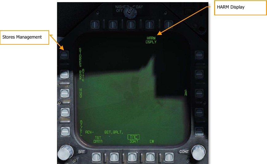
When the HARM is selected in either manner, it will first default to the Self-Protect (SP) mode or the last selected mode. From the SP mode, the other two modes can also be selected: Target of Opportunity (TOO) mode and Pre-Briefed (PB) mode.
On the SMS page, the HARM wingform station will indicate “STBY” if no target has been handed off (H-OFF) to the missile. Once the selected HARM missile has been handed off to a target, the indication changes from “STBY” to “RDY”.
After launch, the next HARM missile in priority is selected automatically. The weapon priority list is: 8 →2→7→3
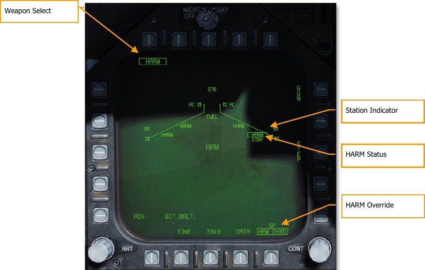
Weapon Select. When at least one AGM-88 is loaded, HARM will appear below pushbuttons 6 to 10. Pressing the HARM pushbutton will box the legend and display the HARM format page.
Station Indicator. HARM is listed below each station that a HARM is attached to. The selected HARM to launch next is boxed.
HARM Status. The launch status of the selected (boxed) HARM is indicated below the station indicator. This can be either STBY or RDY. When the selected HARM is handed off to a target and ready to launch, RDY is displayed.
HARM Override. When boxed, the self-protect pullback mode is inhibited. When unboxed, self- protect pullback mode will activate when a critical threat is detected. Boxed by default. See Self- Protect Pullback Mode, below.
Self-Protect (SP) Mode
How to Employ the AGM-88C HARM in SP Mode
- Master Arm to ARM and Master Mode switch to A/G
- Select HARM from the SMS page
- Press HARM Sequence I to select / cycle detected radar emitters
- With threat emitter boxed on EW Page or EW HUD, press the Weapon Release Button RAlt + Space to launch the missile
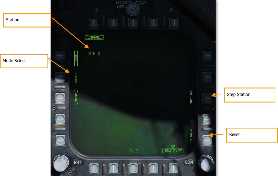
Mode Select. Pushbuttons 3, 4, and 5 are mutually exclusive and used to select the HARM mode. Selecting a mode boxes the legend and an X through the legend indicates that the mode is not available.
Station. The station number of the selected HARM.
STEP. Successive presses of pushbutton 13 cycles through all stations loaded with a HARM.
RSET. Pressing pushbutton 15 cues the HARM to the highest radar threat.
Threat Selection and HUD Indications
If there is more than one lethal or critical SAM or AAA threat detected, pressing and releasing the HARM Sequence button I on the throttle allows the player to cycle through them. Re-select the highest threat emitter by pressing pushbutton 15 (RSET) or the Cage/Uncage Button on the throttle. The selected radar target on the EW displays is indicated as having a box around it. There is no locked target indication on the HARM format page in SP mode.
Once the HARM is launched toward the selected SP target, the next HARM in priority sequence is automatically selected and default to the highest priority threat.
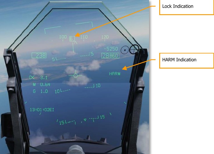
Lock Indication. When the HARM has been cued to an EW detection, a box is draw around the EW emitter code on the HUD, EW Page, and Azimuth Indicator.
HARM Indication. When HARM is selected, HARM is displayed along the right side of the HUD.
Self-Protect Pullback Mode
When the RWR detects a critical threat (either a tracking radar lock, active missile radar lock, or semiactive radar illumination), the Self-Protect Pullback mode will automatically select and prepare a HARM for launch against the detected threat. Note that this functionality is inhibited by default and must be enabled by unboxing the HRM OVRD option on the Stores format.
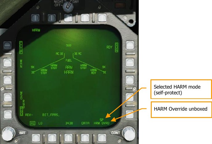
With HRM OVRD unboxed and a critical threat detected, Pullback mode will activate, and the text “HARM” will appear on the HUD and Stores format. If “HARM” is displayed with no X, then pressing the pickle button will immediately launch a HARM against the threat.
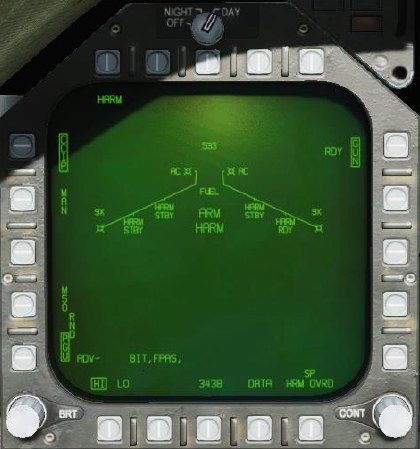
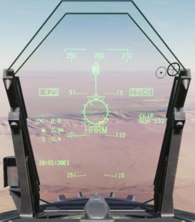
The “HARM” label will be crossed out if the missile is not ready for launch (not powered on, MASTER ARM off, etc.).
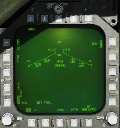
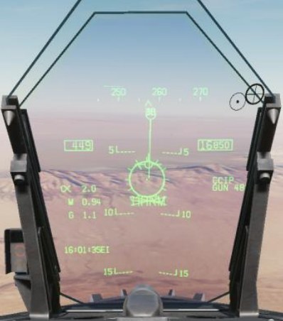
Pullback mode will activate regardless of master mode (A/A or A/G) if the HRM OVRD option is unboxed. If in A/A mode when Pullback is activated, a trigger press will still launch the selected air- to-air weapon.
If the HRM OVRD option is boxed, and Pullback mode is disabled, the text “PLBK” will be displayed instead, and no change will be made to the selected weapon.
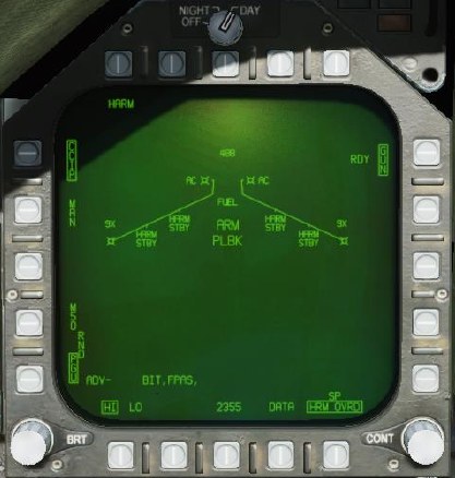
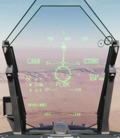
Notes
- Because the HARM has no ranging capability and is not slewed with another sensor in SP mode, there is no range to target provided.
- The HARM is best used at 30,000 feet AGL and above to maximize range.
- If the targeted radar turns off, the HARM will lose guidance and will likely not hit the target.
Target of Opportunity (TOO) Mode
How to Employ the AGM-88C HARM in TOO Mode
- Master Arm to ARM and Master Mode switch to A/G
- Select HARM from the SMS page
- Set TDC to the HARM format page
- Press I to select / cycle detected radar emitters
- Hand-off target to HARM by pressing Cage/Uncage button or C
- With threat emitter boxed on EW Page or EW HUD with H-OFF indication, press weapon release button or RAlt + Space to launch the missile
Unlike SP mode in which targeting is automatic, TOO mode allows the pilot to select a specific target radar, based Class and Type filtering.
The HARM acts as its own sensor and can display up to 15 targets on the TOO HARM display (format). To select a target, the player can cycle through displayed targets via the HARM Sequence button I on the throttle. This is indicated as a box around the target. Once the target has been selected, pressing the cage/uncage button C is used to hand off the Target to the HARM, indicated at a H-OFF above to the Target box. A second press of the cage/uncage button cancels the hand off.
With the target in hand-off, all other Targets on the HARM TOO display are not displayed. With a correct hand off, the HARM on the SMS wingform will change from STBY to RDY and the X through the HARM indication will be removed.
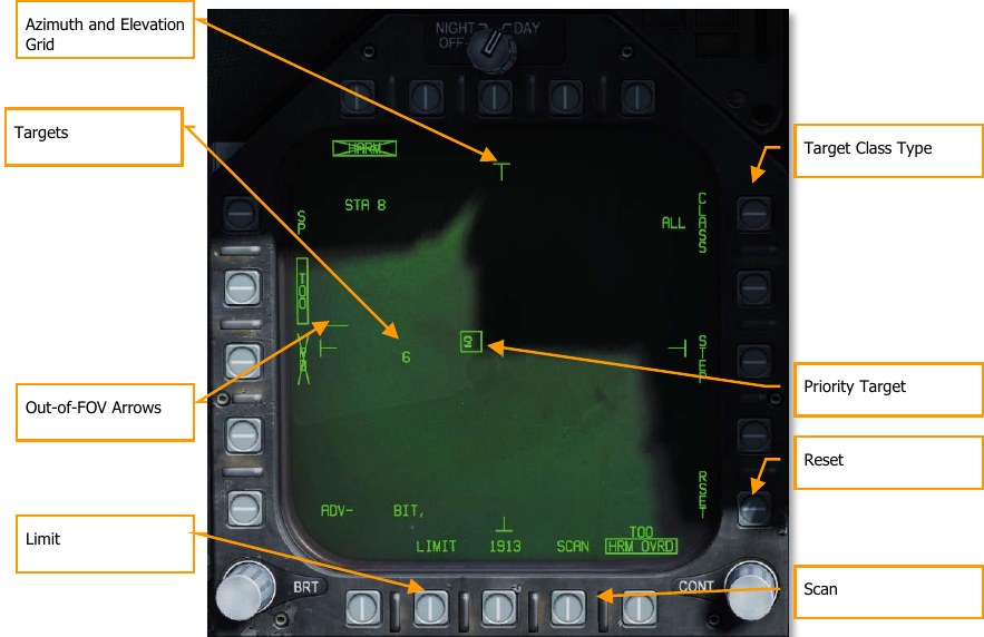
Out-of-FOV Arrows. When targets are detected outside the field of view of the HARM TOO display, arrows are displayed that point in the direction of the unseen targets. Arrows are only at the up, down, left, and right locations.
Azimuth and Elevation Grid. These four “T” markers mark the 30° field of view in azimuth and elevation and are placed near the left, right, top, and bottom of the TOO display.
Targets. All detected targets of the selected target class are displayed in the TOO display as numeric identifiers. Targets are not space stabilized are in reference to the HARM seeker FOV. An “F” preceding a numeric indicates a friendly radar. A half-circle below a target indicates a naval radar, and a horizontal line above the numeric indicates a radar that has locked the player aircraft.
Limit. When selected and boxed, only the 5 highest priority targets are displayed instead of 15.
Scan. When selected and boxed, the HARM Scan sub-level page is displayed and allows the player to view all Classes on the TOO display.
Reset. When pressed, the highest priority target will automatically be selected. This will cancel a target handoff.
Priority Target. The priority target has a box around it, and the priority target can be cycled using the HARM Sequence switch on the throttle. Setting the Priority Target can also be done with the TDC. This will initially default to the first target detected of the selected target type.
Target Class Type. To the left of the CLASS legend, the Class selection is indicated from the Scan sub-level page. TT in the image below. When pressed, the Type sub-level page is displayed.
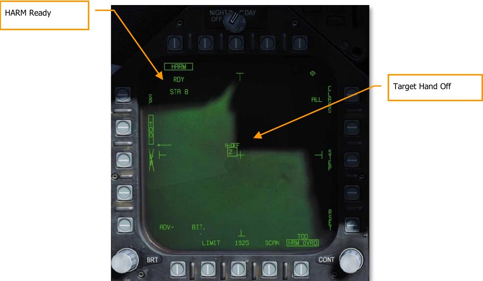
TOO HUD
When a target has been designated on the HARM TOO display, a line of sight to the target box is displayed on the HUD. Once the target is handed off to the HARM, H-OFF appears above the box. A second press of the cage/uncage button C cancels the hand off.
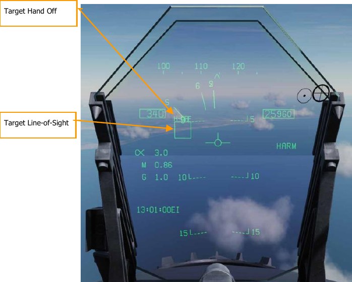
EW Indication
When a Target has been designated, the Target symbol on both the EW DDI page and the EW HUD will also have a box around the indication.
Class Sub-level Page
The Class sub-level page (pushbutton 11) allows the player to filter the Class of targets that are displayed in the TOO display. From the right, top, and left DDI pushbuttons, the player can select any of these. When one is selected, the page is automatically changed back to the TOO page with the selected Class code is displayed to the left of the Class legend.
On the Class page, all detected targets of all classes are listed as filled circles and their Class code is displayed to the left. If the target is right or left of the HARM FOV, arrows are drawn to show the direction of the target outside the HARM FOV.
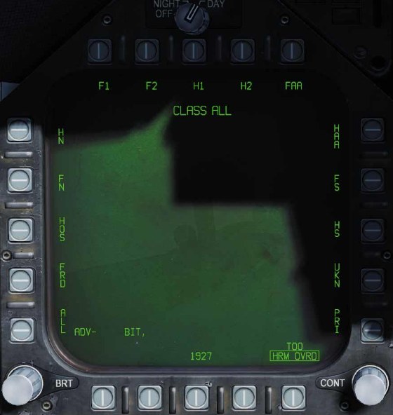
- Class Legend. Indicates the selected Class.
-
Class Selections. Along the left, top, and right DDI pushbuttons are 15 Class selections. These are each two or three-digit codes. DCS uses the following substitutes:
- ALL. All classes of radars
- FRD. Friendly radars
- HOS. Hostile radars
- FN. Friendly naval radars
- HN. Hostile naval radars
- F1. Old friendly radars
- F2. New friendly radars
- H1. Old hostile radars
- H2. New hostile radars
- FAA. Friendly AAA
- HAA. Hostile AAA
- FS. Friendly search radars
- HS. Hostile search radars
- UKN. Unknown radars
- PRI. Radars locked to player aircraft
Each Class can have multiple radars that fall within the Class. For a list of classes that apply to each radar, see ALIC Codes.
Scan Sub-Level Page
When Scan is boxed from pushbutton 17, the Scan sub-level page is displayed. This will display all Classes and each Class that is currently being detected by the radar warning receiver. Each detected class is indicted by a filled circle with its class code to the right. If the Class is detected outside of the HARM field of view, then arrows will be to the left or right of the filled circle to indicate off-FOV direction.
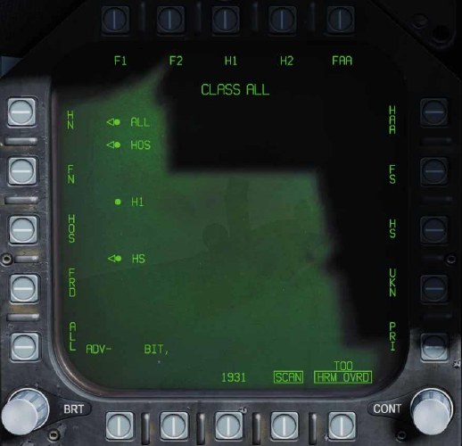
As with the Class sub-level page, the user can also select a Class from this page. In so doing, it will also revert to the HARM TOO page.
Pressing the Scan button will return the display to the TOO page.
Pre-Briefed (PB) Mode
How to Employ the AGM-88C HARM in PB Mode
- Master Arm to ARM and Master Mode switch to A/G
- Select HARM from the SMS page
- Box “PB” on the HARM format to enable PB mode (pushbutton 3)
- Press “UFC” on the HARM format (PB 14).
- On the UFC, select line 4 (TGT), enter the three-digit code for the emitter type, and press ENT.
- Select either aircraft pull-up (PB 2) or HARM pull-up (PB 1).
- Select and designate the waypoint over the target location.
- Press and hold the weapon release button or RAlt + Space while following the HUD cues. When the FPM intersects the launch cue within 1° of the azimuth steering line, the missile will launch.
Pre-briefed mode is used when the location of the enemy emitter is known, and a waypoint has been placed in the vicinity of that location. In pre-briefed mode, the missile will loft and fly to the location of the emitter, then turn on its receiver and home on the target.
Activate pre-briefed mode by boxing “PB” (pushbutton 3) on the HARM format. The pre-briefed mode symbology will be displayed.
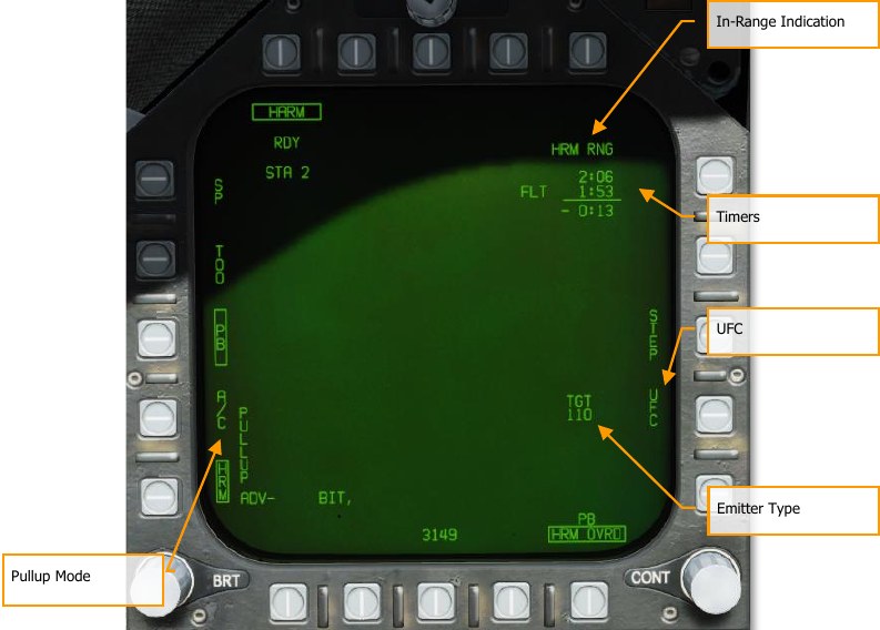
Pullup Mode. When “HRM” is boxed, the HARM will do all maneuvering (including lofting) to reach the target. The aircraft will have to be close enough that the HARM will have sufficient energy to do all the necessary maneuvering. When “A/C” is boxed, it is expected that the pilot will perform the loft maneuver, increasing the HARM’s range.
In-Range Indication. Displays “A/C RNG” when the aircraft is in-range for an A/C pullup shot. Displays “HRM RNG” when the aircraft is in-range for a HARM pullup shot.
Timers. The top line displays the time-of-flight of the next HARM, if launched now. The second line displays the time-to-impact of the in-flight HARM. The bottom line displays the difference between the two; in other words, how much later the second impact would be after the first.
UFC. Pressing this pushbutton allows the pilot to set the emitter type on the UFC.
Emitter Type. Displayed once an emitter type has been set. Emitter types are listed in ALIC Codes.
Initially, with no target type set, the HARM moniker will be crossed out and no launch will be possible. The pilot must first enter a target type before HARMs can be employed in pre-briefed mode.
To enter an emitter type, press the “UFC” pushbutton (PB 14), and select line 4 on the UFC:
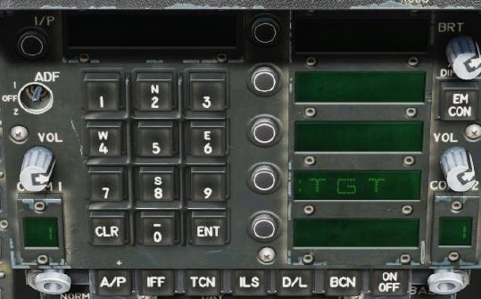
After selecting line 4, enter the 3-digit emitter type code and press ENT.
After entering a target type and choosing a pullup mode, use the HSI format to select the waypoint at or near your target location, and box “WPDSG” to designate it. You should then see the timer block at the upper-right. The HUD will provide steering cues to the launch zone.
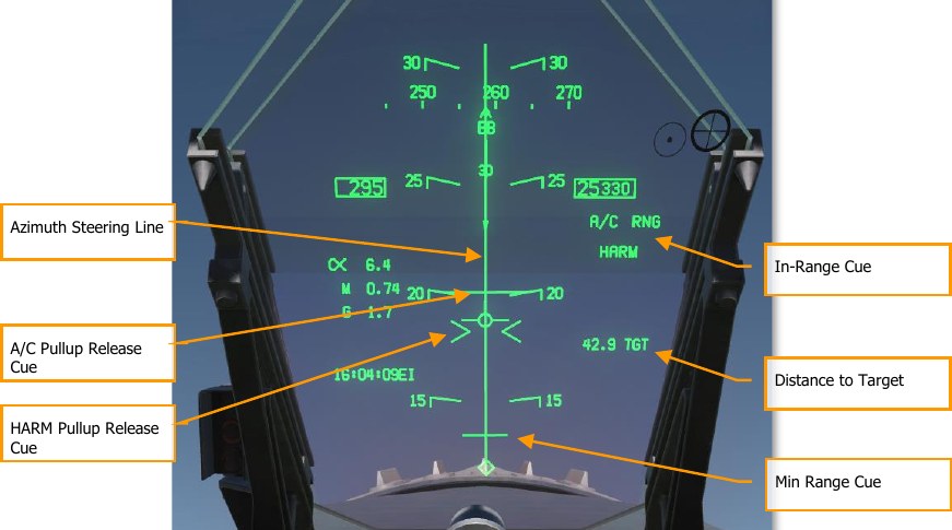
If you are performing an aircraft pullup, fly towards the target according to the azimuth steering line (ASL) until “A/C RNG” appears on the HUD and DDI. Then, begin your loft maneuver. While holding down the Weapon Release button, raise the nose to 45° and climb until the flight path marker intersects with the A/C pullup release cue. Once it does, the HARM will come off the rail. You can release the Weapon Release button at this point.
If you are performing a HARM pullup, fly towards the target according to the ASL until “HRM RNG” appears on the HUD and DDI. Then press and hold the Weapon Release button. Raise the nose until the FPM intersects with the HARM pullup release cue. (A small amount of loft may be required.) The HARM will come off the rail, and you can release the Weapon Release button.
The missile will not fire unless the FPM intersects with the appropriate range cue and the flight path marker is within 1° laterally of the azimuth steering line.
When the FPM intersects the min-range cue, the aircraft is too close to the target. The HARM missile will not be able to perform the required pull-down to reach the target.
AGM-84D Harpoon
The AGM-84D Harpoon is the primary anti-ship weapon for the Hornet. It is a big, heavy weapon with a large warhead, sophisticated guidance system, and a long range. It has two primary release modes: Range / Bearing Launch (R/BL) and Bearing Only Launch (BOL). R/BL is the most accurate of the two but requires you to know the bearing and range to the target before firing. This is done using the SEA mode of the radar on AG mode. BOL is a less accurate, but you only need to know the approximate bearing of the target. For this initial release of the Harpoon, BOL will be available. Once the SEA mode of the radar is ready, we will add R/BL mode.
The weapon release button RAlt + Space is used to launch a Harpoon.
Harpoon SMS Format
Upon selection of the AGM-84D Harpoon from the top row of the SMS page, the Harpoon format page is displayed. Options this page will vary based on BOL or R/BL mode and if a Harpoon Turnpoint (HPTP) is used.
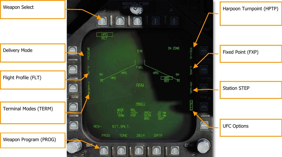
The unique and primary functions of the page are:
Weapon Select. Harpoons are listed as HPD and will first have a 20-second TIMING cue when first selected. Once the 20-second count-down has expired, RDY is displayed below the HPD indication. Prior to being ready, the boxed HPS will have an X through it.
Delivery MODE. There are two modes that the Harpoon cane be fired in:
- BOL. Bearing Only Launch (BOL) allows the missile to be launched and fly along a set bearing and the missile will attempt to search for ship targets according to the set criteria.
- R/BL. Range / Bearing Launch (R/BOL) requires a ship target to first be designated (using A/G radar SEA mode.
Flight Profile (FLT). The FLT option provides three flight profiles, HIGH, MED, and LOW. These are used to change the flight profile setting.
- HIGH: The Harpoon cruises to the target at high altitude. A high-altitude profile provides the maximum range for the weapon and increases the effective search area of the seeker; however, the weapon is detectable at longer range and more susceptible to countermeasures. Cruise altitude is 35,000 feet.
- MED: The Harpoon cruises to the target at medium altitude. Medium altitude provides a compromise between the HIGH and LOW profiles. Maximum range and search area is greater than LOW, but less than HIGH. Similarly, enemy detection typically occurs later than HIGH, but sooner than LOW. Cruise altitude is 15,000 feet.
- LOW: The Harpoon cruises to the target at low (sea skimming) altitude. Low altitude is also known as a sea skimming profile because the Harpoon travels to the target area at very low altitude. While maximum range is reduced, enemy reaction time is also greatly reduced. Cruise altitude is 5,000 feet.
Terminal Modes (TERM). Two terminal mode options, SKIM and POP, are available. These are used to change the terminal mode option.
- SKIM: After acquiring a target with its onboard radar, the Harpoon flies a minimum altitude approach to the target (25 feet).
- POP: After target acquisition, the missile commences a pop-up attack on the target. This begins at 5 nm from the target and climbs to 500 feet before diving on the target.
Seek Mode (SEEK). This is only available in R/BL mode and not pictured above. Upon pressing SEEK, three options are presented that determine when the seeker begins searching for the target at the designated location:
- SML. 10,000 meters before target location
- MED. 20,000 meters before target location
-
LRG. 30,000 meters before target location
- LEFT
- RIGHT
- NORM
- NEAR
- FAR
This will offset the search based on the selection.
Harpoon Turnpoint (HPTP). Allows the selection of a waypoint or markpoint to be used as an intermediate turnpoint between ownship and the target/search area. With a turnpoint selected, the Harpoon will first fly to the turnpoint, then turn towards the final bearing (BOL), or target (R/BL). Boxing the HPTP option copies the currently selected (via HSI) waypoint/markpoint into the selected
Harpoon delivery program. To change the turnpoint, the HPTP option is unboxed, the waypoint is changed via the HSI, and then the HPTP option is re-boxed. The HPTP option is applicable to both the R/BL and BOL modes, however in BOL mode, the search distance becomes relative to the turnpoint rather than ownship. If a HPTP is selected in BOL mode, the Fixed-point option is blanked, since the two modes are incompatible.
Fixed-Point (FXP). The Fixpoint option allows the ability to fix the search pattern of the BOL mode about a NAV stabilized mid-point. The mid-point is located halfway between the search and destruct ranges. This essentially creates a fixed derived “target” area allowing multiple Harpoons to be deployed into the same area without an actual designated target. The fixpoint option is not available when a turnpoint (HPTP) is selected.
Station STEP. Actuation of the Step PB cycles through loaded Harpoons on the wing stations. A selected and TIMED Harpoon will have its HPD label boxed on the wingform with RDY below. Non- selected stations are not boxed and have STBY below.
Weapon Program (PROG). This option cycles between the available programs in sequence. You can modify the current program by using the MODE, FLT, TERM, SEEK, SRCH, and BRG settings. There can be up to five programs and each Harpoon can be set to a different program.
TTMR. The Time to Maximum Range (TTMR) is displayed only in R/BL mode when the target is locked and indicates time remaining until the target will be at maximum launch range. When target is within maximum range, the TTMR is replaced with IN ZONE. This is displayed in the top left corner of the Harpoon format page.
UFC Options
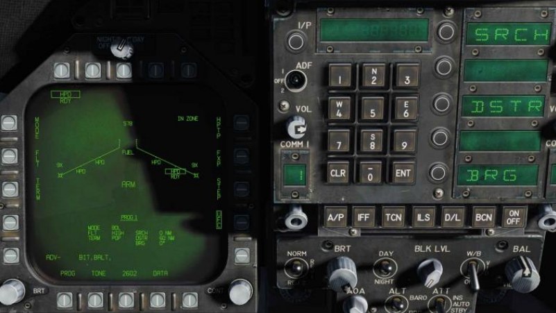
Active Search Range (SRCH): (BOL mode only) This option adjusts the range from the launch point that the Harpoon begins its active search. To adjust, the player will press the UFC pushbutton and then select the SRCH button on the UFC. The player can then enter a value on the keypad and then press the UFC ENT button to save it. Valid search range is from 0 to 105 nm.
Missile Destruct Range (DSTR). Upon selection from the UFC Option Select Window, the player can enter a range in nautical miles on the keypad to determine when the Harpoon will self-destruct. Valid range is from the entered search range plus 172 nm.
Flight Bearing (BRG): (BOL mode only). As with the SRCH function, the player will select the BRG option on the UFC. The magnetic or true bearing relative to ownship that the Harpoon will launch along. If a Harpoon Turnpoint (HPTP) is selected, the bearing will be relative to the turnpoint. If Fixpoint (FXP) is selected, the BRG will become irrelevant. Valid bearing is 0 to 359.
Harpoon HSI
Once the search, destruct, and bearing information has been entered the program for a Harpoon, a graphic of its flight plan is displayed on the HSI.
When no Harpoon Turnpoint is selected, the HSI will display a line based on the entered bearing, a small hash mark on the bearing line that indicates the start of the search, and an “X” at its self- destruct point.
With a Harpoon Turnpoint, the bearing, search, and destruct symbols are in relation to the selected waypoint that acts as the Harpoon Turnpoint.
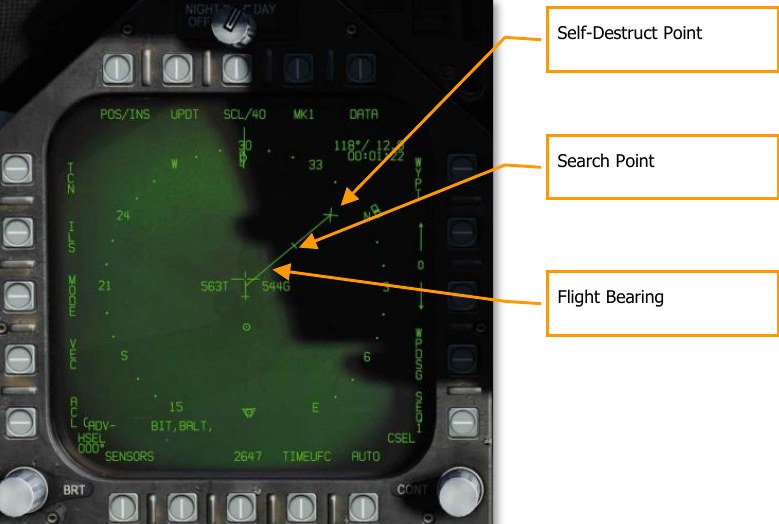
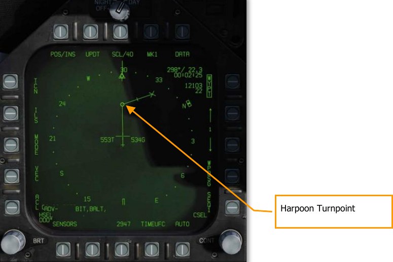
Harpoon HUD
When a Harpoon is selected, the HUD symbology reflects the weapon and mode selected.
When BOL mode is selected, only the mode, BOL, and the weapon identification, HPD, are listed along the right side of the HUD. As there is no designated target, there is no TGT indication like range and bearing to target.
If the weapon is with a valid launch zone to reach its programed search and destruction zone, an IN ZONE indication is displayed. If, however, the missile is out of valid launch parameters, an OFF AXIS message is displayed.
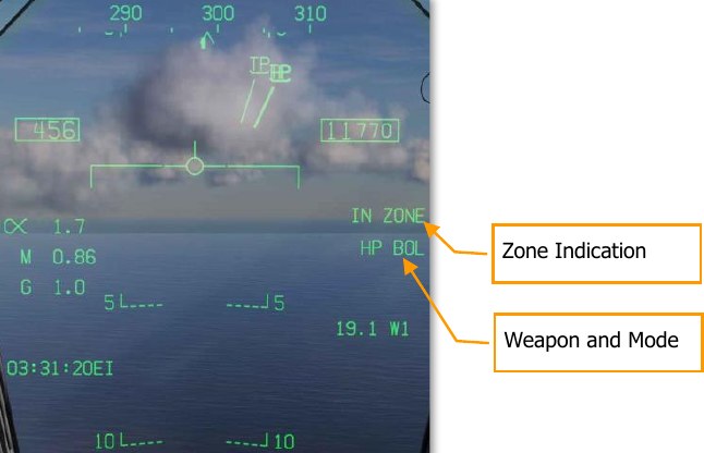
AGM-84E Stand-Off Land Attack Missile (SLAM)
The AGM-84E SLAM is a derivative of the AGM-84D Harpoon anti-ship missile that is designed for precision attack against fixed ground locations. It is a sub-sonic (0.7 Mach) cruise missile with an operational range of 50 miles that uses INS and GPS navigation. It is armed with the same warhead as in a Tomahawk land attack missile (TLAM). Like the AGM-62 Walleye that preceded it, it interfaces with the AN/AWW-13 datalink pod that allows live video from its AGM-65F seeker to be transmitted to the pilot while the missile is in flight. Using the TDC slew control, the pilot can fly the missile to the target with pinpoint accuracy. Like other GPS-guided weapons of the Hornet, the SLAM can be launched in both Pre-Planned (PP) and Target of Opportunity (TOO) modes.
The AN/AWW-13 Advanced Datalink Pod is used to communicate with the SLAM. It allows for guidance of the SLAM seeker after it has been launched by transmitting and receiving post-launch slew and lock-on commands. The AN/AWW-13 provides man-in-the-loop guidance.
The weapon release button RAlt + Space is used to launch a SLAM.
Weapon Selection
Upon initial weapon selection and timing is complete (2:30), all currently inventoried weapons of the same variant are placed into STBY (standby) status as indicated under their respective weapon acronyms. All weapons simultaneously begin warming up and will remain initialized if at least one weapon station of the same type is selected.
Deselecting SLAM will likewise cause all weapons of the same type to spin down, requiring at least 2.5 minutes for warmup to complete again. Consideration should therefore be given to this warmup cycle when mission planning. The status of this warmup cycle is indicated on the STORES and SLAM formats as a TIMING cue which is initialized to 10:00 minutes and counts down. The TIMING cue is removed when the Time-to-Go (TTG) reaches 7:30 (warmup complete after 2:30).
When a GPS weapon is initially selected, all stations of the same store type are simultaneously placed in STBY until the TIMING cue is removed, at which point the priority station will either remain in STBY or transition to RDY (ready), depending on A/G Ready status (e.g., warmup complete, designation exists and is valid). All additional stores of the same type will remain in STBY until selected (RDY cue), explicitly deselected, or indirectly deselected by the selection of a different weapon type or upon transition to A/A master mode.
SLAM Stores Format
As with other A/G stores, all GPS weapons including SLAM may be selected in NAV or A/G master modes by boxing the applicable weapon acronym from weapon selection menu across the top row of push buttons from the STORES planform format. It should be possible to program SLAM while on the ground with master arm to SAFE and in NAV master mode.
SLAM is listed as SLAM 🤔
Selection of any GPS weapon on the STORES format applies power to every inventoried GPS weapon of the same type. Power remains applied to the GPS weapons until deselected. A GPS variant is deselected only when the associated weapon select option is unboxed explicitly, or another weapon type is selected. When operational power is first applied, warm-up and transfer alignment begin. As soon as warmup is complete (2.5 minutes from initial power up), the weapon may be armed for release. Note that the alignment quality is not a prerequisite for release interlocks and achieving an alignment quality of GOOD may take as long as 10 minutes.
SLAM and Datalink SMS Page
Because of the possible combinations of loading SLAM and the AN/AWW-13 datalink pod, there are three possible format pages. These formats replace the standard wingform format when selected.
- Only datalink pod
- Only SLAM
- Both datalink pod and SLAM
From the TAC page SLAM DSPLY is available when only at least one SLAM is loaded but not AN/AWW-13 datalink pod. SLAM-13 DSPLY is shown when both a SLAM and the datalink pod are loaded, and DL13 DSPLY when only the datalink pod is loaded.
When both SLAM and the datalink pod are selected, only the top 80% of the displays has video with stroke symbology over the entire display.
AN/AWW-13 Datalink Pod Only Selected
When the datalink pod is selected and a SLAM is not, the top 80% of the display should be static because the datalink pod has not been linked to a SLAM. Elements of the datalink only page include:
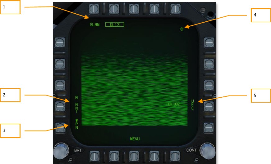
- Weapon Selection Status. If the AWW-13 is being used in conjunction with a SLAM, both SLAM and DL13 should be boxed. When conditions do not permit release of a SLAM (e.g., out of LAR), “SLAM” is crossed out.
- Pod Antenna Option. The A ANT option selects the aft antenna of the datalink pod. It is boxed when selected. Although it can be selected, it will have no game function.
- Weapon Selection. The Weapon option links the datalink pod to the selected datalink- capable weapon. When linked, the option is boxed.
- TDC Assignment Indication. This diamond indicates that the TDC is assigned to the display. In order to slew the seeker head, TDC must be assigned to the DL13 format.
- UFC Pod Channel Selection Option. This option is used to select one of the pre-set pod datalink channels. Pressing PB 14 displays CHNL on the top Open Select Window on the UFC. Upon colonizing the window, the channel is entered using the keypad and ENT is pressed. If a valid channel is entered (2, 3, 7 or 8), the channel number is listed after CH on the datalink format. The channel number will correspond to the SLAM station number.
SLAM Employment with No Datalink Pod
When used without the AN/AWW-13 datalink pod, the SLAM acts in a very similar manner to other INS/GPS-guided weapons like JDAM and JSOW, in both TOO and PP modes. The terminal infrared imager cannot be used without a datalink pod.
SLAM SMS Format with No Datalink Pod
Upon selection of the AGM-84E SLAM from the top row of the SMS page, the SLAM format with AN/AWW-13 datalink pod page is displayed.
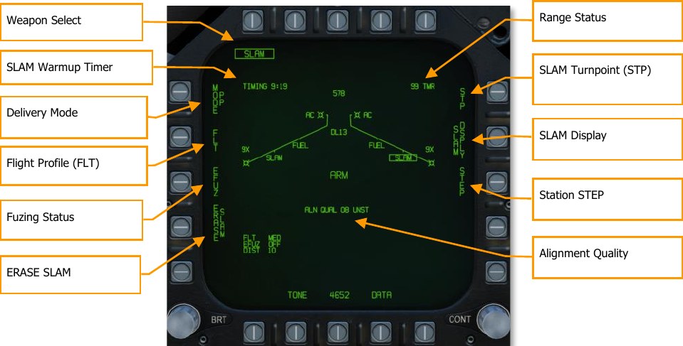
The unique and primary functions of the page are:
Delivery Mode. Selects the GPS delivery mode for the priority station.
- Pre-Planned (PP). Instructs the priority weapon to execute the selected pre-planned mission, if valid.
- Target of Opportunity (TOO). Instructs the priority weapon to cue to the sensor-designated target, if any.
Weapon Select. SLAMs are listed as “SLAM” and will have a 2 minutes and 30 seconds TIMING cue when first selected. It will start at 10:00 and countdown to 7:30 until GOOD alignment is reached. Once at 7:30, RDY is displayed below the SLAM indication. Prior to being ready, the boxed SLAM will have an X through it.
SLAM Warmup Timer. The TIMING SLAM warmup timer cue initializes at 10:00 minutes and counts down to 7:30 when SLAM warmup is complete, at which time the cue is removed.
Flight Profile (FLT). The FLT option provides three flight profiles, HIGH, MED, and LOW. These are used to change the flight profile setting.
- HIGH: The SLAM cruises to the target at high altitude. Cruise altitude is 35,000 feet.
- MED: The SLAM cruises to the target at medium altitude. Cruise altitude is 15,000 feet.
- LOW: The SLAM cruises to the target at low (sea skimming) altitude. Cruise altitude is 5,000 feet.
The default Flight Profile setting will be Medium (MED), and the selected Flight Profile is listed in the bottom left portion of the page.
Fuzing Status. The EFUZ or MFUZ fuze status cue indicates the armed or safe status of the fuzes for the selected SLAM. The fuze status is displayed in the bottom left corner of the display.
ERASE SLAM. This option immediately clears all GPS weapons of the selected variant of all previously entered pre-planned (PP) mission data. SLAM ERASE is boxed when selected and remains boxed for 5 seconds. SLAM ERASE cannot be undone.
SLAM Turnpoint (STP). Allows the selection of a waypoint or markpoint to be used as an intermediate turnpoint between ownship and the target/search area. With a turnpoint selected, the SLAM will first fly to the turnpoint, then turn towards TOO or PP target location. Boxing the STP option copies the currently selected (via HSI) waypoint/markpoint into the selected SLAM mid-course guidance program. To change the turnpoint, the STP option is unboxed, the waypoint is changed via the HSI, and then the STP option is re-boxed.
Station STEP. Actuation of the Step PB cycles through loaded SLAMs on the wing stations. A selected and TIMED SLAM will have its SLAM label boxed on the wingform with RDY below. Non- selected stations are not boxed and have STBY below.
Range Status. The Range Status cues refer to the weapon at the priority station:
- ## TMR. If the aircraft is outside the Launch Acceptability Region (LAR) and the target is within the forward hemisphere of the aircraft, this cue will read ## TMR indicating the time in seconds (99 max) until the aircraft is within the maximum range of the weapon at the current (no launch zone specified), or reference (LZ specified) altitude.
- IN RNG. If the aircraft is within the aerodynamic range of the weapon, but is not yet within the LAR, IN RNG will be displayed here. Generally speaking, and at least in terms of the current simulation, IN RNG will be transient, as IN ZONE will occur almost immediately following IN RNG.
- IN ZONE. This cue indicates the aircraft is within the LAR and the weapon should be released.
Alignment Quality. Indicates the priority station navigational state. This is the state of the weapon’s internal guidance alignment status. Weapon INS alignment quality takes time to improve.
This cue consists of a numeric value from 01 (best) to 10 (worst) and a plain language cue of UNST, MARG or GOOD. All weapons initialize in the 10 UNST state.
- Time 10:00 to 9:15: ALN QUAL 10 to 7, UNST
- Time 9:15 to 8:30: ALN QUAL 6 to 3, MARG
- Time 8:30 to 7:40: ALN QUAL 2 to 0, GOOD
TTMR. The Time to Maximum Range (TTMR) is displayed only when a TOO or PP target has been set for the selected SLAM. It indicates time remaining until the target will be at maximum launch range. When target is within maximum range, the TTMR is replaced with IN ZONE. This is displayed in the top left corner of the SLAM format page.
SLAM DSPLY. Selecting SLAM Display changes the SLAM format page to Quantity page.
Weapon Quantity and Mission Option Sub-Level
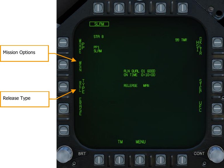
Mission Options. This page allows the player to create Target Data Sets (TDS) for the selected SLAM against the selected target. The Mission Data (MSN) format is accessed by pressing the MSN option at pushbutton 4. The Mission Data format is used to select and program one of the 6 available PP missions or a TOO target. A mission is selected by depressing one of the PP# options at PB6- PB11 if PP mode is selected. If in TOO mode, the target is based on designated target location. One of the various UFC options along the lower right side of the format is then selected to begin program data entry. Note that program data may be pre-programmed in the Mission Editor.
Release Type. This cue lists the selected release mode for the selected weapon:
- AUTO LOFT: N/I
- MAN: Weapon release is initiated manually by the pilot.
- FD: N/I
Pre-Planned Mission Programing Sub-Level
Once the Mission Option is selected for a PP or TOO attack, the mission programming page is displayed.
Pre-Planned allows entry of specific target coordinates as well as optional offset coordinates and/or Launch Point parameters. These options are combined into what is referred to as a Pre-planned (PP) Mission. There is a total of 6 PP missions available for programming and each weapon station may be assigned to any one of these missions. The Launch Point (LP) for any given mission is optional and is automatically calculated based on pilot-entered bearing, altitude, and ground speed. The MC then determines the maximum range of the weapon at the reference altitude and converts the resulting point into LP coordinates. The aircraft is then flown to the LP along the LP bearing line to deliver the weapons at a specific bearing to the target(s). A PP mission is selected by boxing one of the 6 available PP mission pushbuttons located along the top of the MSN display. Unboxing a currently boxed PP mission, selects the TOO mode.
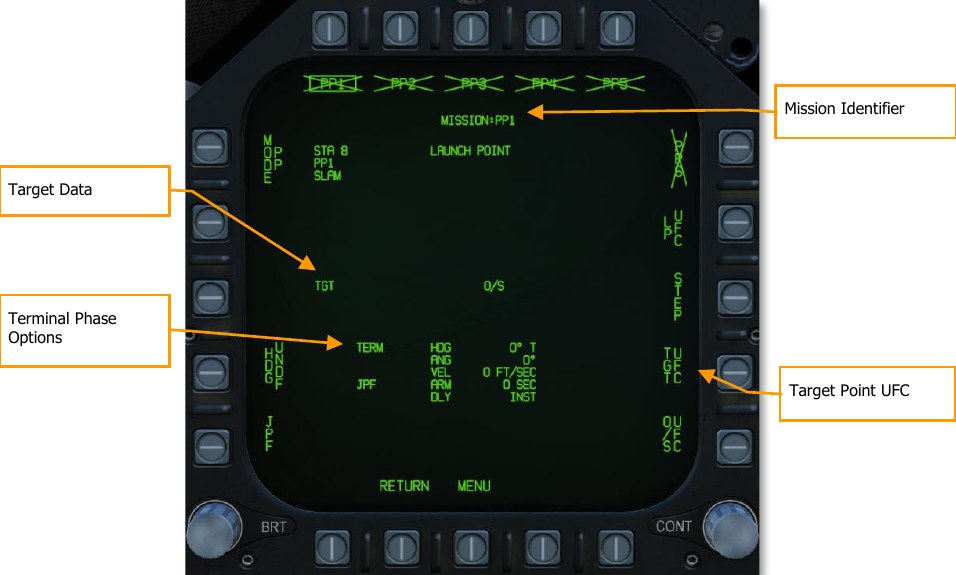
Mission Identifier. This area displays the currently selected mission type (PP or TOO), and in the case of a PP mission, the mission index. For example, PP4.
Target Data. The target coordinates and elevation for the selected PP mission may be specified via the UFC, and if valid, are displayed here. They may also be set as a preplanned target created in the Mission Editor. If the target is an OAP (an offset was specified), the TGT label becomes OAP, and the OAP relative bearing and distance are displayed to the right of the OAP data area. The latitude and longitude of the target are displayed in this data block, as well as target elevation.
Target Data UFC Format. Upon selecting the Target Data UFC Entry pushbutton 14, you will use the UFC to enter the target coordinate and elevation for the selected PP mission.
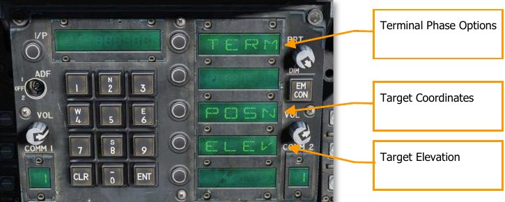
POSN is the lat / long coordinate of the target. This is entered as longitude and longitude in degrees, minutes, and seconds.
ELEV can be entered in FEET or MTRS (meters). Valid range for FEET is -328 to 32808 and MTRS is - 100 to 10000. We will skip MSL or WGS selection as pictured below. Once a valid elevation and target coordinate have been entered and saved, the selected PP mission will no longer have an “X” through it and the TGT (target) information on the MSN screen will be complete.
Terminal Phase Options are entered as the weapon impact angle, weapon impact heading, and weapon impact velocity. Selecting TERM displays three options on the UFC for:
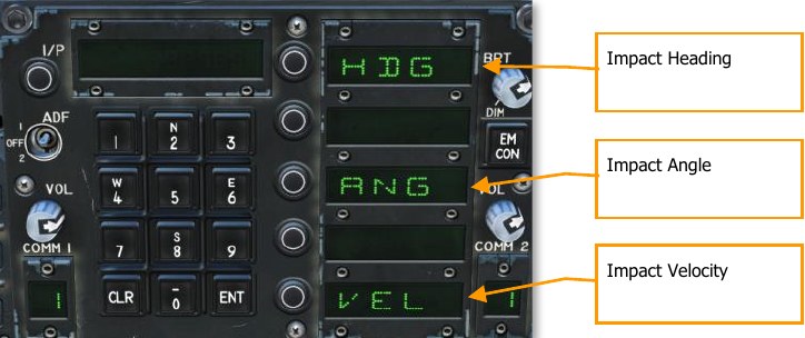
- HDG. Heading of weapon at time of impact. Valid range if from 0° to 359°.
- ANG. This is the impact angle of the weapon. Valid range is 0° to 90°.
- VEL. Velocity at impact. Valid range is 100 to 26800 feet per second.
Target of Opportunity Mission Programing Sub-Level
When the mission option is set to TOO, the mission planning screen regarding the target being the designated location (designated waypoint or target point). The page options are like that of the PP mission planning screen, but with the following changes:
- No programable pre-planned missions
- No target UFC option; only terminal phase as described above
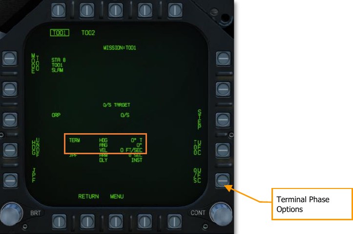
SLAM and Datalink Pod Combined Employment
When the AN/AWW-13 datalink pod is paired with the SLAM in combined form, in provides use of the infrared imager. This entails minor changes to the format pages but adds video display.
Upon selection of the AGM-84E SLAM from the top row of the SMS page, the SLAM format without AN/AWW-13 datalink pod page is displayed. Each SLAM needs to be individually paired with the datalink pod:
- From the SLAM format page, both SLAM and DL13 (datalink) pod must be selected and boxed from pushbuttons 6 to 10.
- With SLAM and the DL13 selected, pressing WEP at pushbutton 15 boxed the option and displays up to four SLAMs next to pushbuttons 2 to 5.
- Selected the displayed SLAM within pushbuttons 2 to 5 pairs that SLAM to the DL13, and SLAM is displayed below DL13 at pushbutton 8. Once paired, WEP becomes unboxed.
New elements of the combined SLAM DL13 format page include:
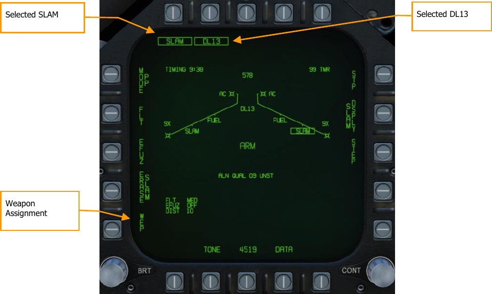
Weapon Assignment. Pressing pushbutton 15 selects (boxes) the option and will display available SLAMs available for pairing to the datalink pod.
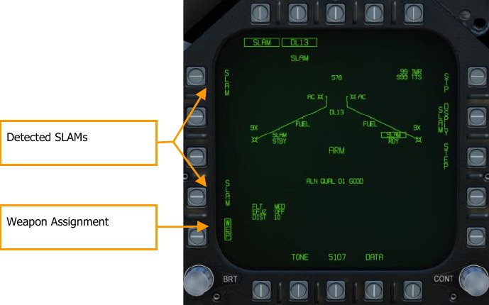
Time to Seeker (TTS). Once a SLAM has been paired to the datalink pod, a valid PP or TOO target has been set, and a seeker activation distance has been entered, a TTS field is displayed that counts down in seconds the time to the time the seeker will activate. This can range between 001 and 999.
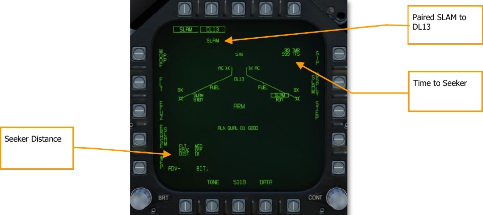
Seeker Distance. Once the missile and the datalink pod have been paired, the seeker activation distance is displayed in the bottom left corner of the display. The default value is 10 nm.
Weapon Quantity and Mission Option Sub-Level
This sub-level page functions the same as the SLAM without datalink pod except it adds a Seeker Activation UFC option that determines the range from target that the terminal seeker will activate.
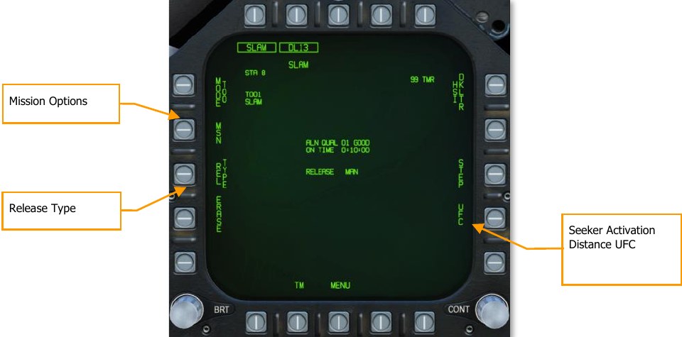
Mission Options. This page allows the player to create Target Data Sets (TDS) for the selected SLAM against the selected target. The Mission Data (MSN) format is accessed by pressing the MSN option at pushbutton 4. The Mission Data format is used to select and program one of the 6 available PP missions or a TOO target. A mission is selected by depressing one of the PP# options at PB6- PB11 if PP mode is selected. If in TOO mode, the target is based on designated target location. One of the various UFC options along the lower right side of the format is then selected to begin program data entry. Note that program data may be pre-programmed in the Mission Editor.
Release Type. This cue lists the selected release mode for the selected weapon: AUTO or MAN.
Seeker Activation Distance UFC. This enables entry of the distance from target at which the seeker display activates.
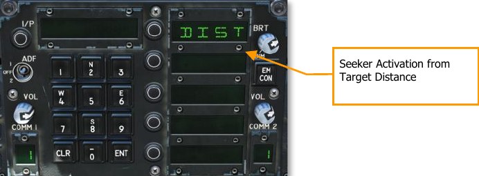
SLAM Terminal Seeker
Once the Time to Seeker time reaches zero and the DDI is set to the SLAM format page, the page will be replaced by the video image from the SLAM terminal seeker. This is a modified version of the infrared seeker as used for the AGM-65F. Upon the seeker video being displayed, the pilot may uncage the seeker and lock it to a contrasting target. Upon seeker lock, the SLAM will steer to intercept the target.
Seeker video is displayed over the entire SLAM display, with stroke written symbology displayed over the weapon video. The video display format includes the following:
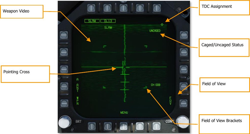
Weapon Video. Composite Video will be routed to displays with the video format selected. In addition to the IR scene, missile video shall include symbology for seeker position, a good lock indication, tracking polarity indication, FOV indication, and seeker depression indication. If the missile loses track or does not manage to lock-on to a target, a break-lock condition will occur. The missile will then go into correlation track (video crosshairs will retract to the edge of the display) and will remain there until either a cage/uncage or a TDC action slew. Note also when the missile is in track mode, an exclusion window is placed around the target, within which the large crosshairs and the pointing cross will not be displayed. If the pointing cross should fall within this tracking window, then the portions of the cross that fall within the region will be blanked.
Pointing Cross. The seeker position will be indicated by a small pointing cross. The pointing cross position relative to the large crosshairs will indicate the seeker position. Relative to missile boresight the tick marks along the vertical crosshair are spaced by 5°, thereby indicating the depression angle and the scale. When the seeker is in track and either the target is not within the launch constraint window or the tracking performance is poor, the small pointing cross will flash. A steady pointing cross will indicate a good lock.
TDC Assignment. This diamond-shaped symbol appears in the upper right corner of the display whenever the TDC is assigned to the SLAM.
Field of View. The IR video will initialize to wide FOV. While the seeker is not in Track mode, the FOV (FOV) options can be toggled via two methods. The FOV can be changed by selecting FOV option on the Maverick format, or by the throttle outboard switch (HARM Sequence/FLIR FOV/RAID).
Field-of-View Brackets. The video display will place four corner brackets within the wide FOV indicating what area will be encompassed in narrow FOV. The corner brackets are not displayed in narrow FOV.
Caged/Uncaged Status. The caged/uncaged status of the weapon is continuously provided on the video format. when the weapon is initially selected with no existing designation, CAGED is displayed. when an uncage signal is commanded to the missile (by depression of the uncage switch, selection of the Forced Correlate option, action slewing of the TDC, or by making a designation), UNCAGED is provided on the format.
SLAM HSI Format
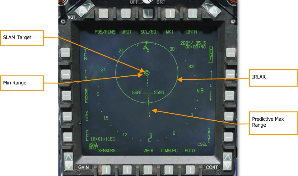
SLAM Target. This is a solid triangle symbol at the location of the PP target location, or a solid diamond if a TOO target location. The symbol shows the last selected PP or TOO mission.
Minimum Range. This is a circle that is centered on the target and indicates the minimum acceptable launch radius of the selected SLAM. This cue is not displayed when the aircraft is within the IZLAR.
In Range LAR (IRLAR). This larger circle is also centered on the target and represents the range at which the selected SLAM can be launched under current flight conditions (heading, altitude, and airspeed) and provide a minimum impact angle of 35° and a minimum impact velocity of 300 feet per second. This cue is removed when the aircraft is within the IRLAR.
Predictive Max Range. This dashed line indicates the absolute maximum launch range to the target, not accounting for impact angle and speed. This will always be greater than the IRLAR. The line will run from the target and through the ownship. At the end of the dashed line is a bar. This bar should always be at the best-case maximum range for a SLAM.
SLAM HUD
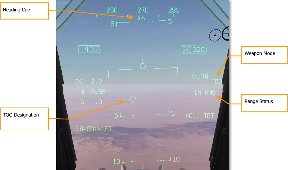
Heading Cue. This cue on the heading tape provides steering direction to the IZLAR. If a release quantity of more than 1 is selected, this cue is not displayed and the waypoint or TACAN cue is displayed instead.
TOO Designation. Diamond system that indicates the line-of-sight location to the TOO TGT. When in PP mode, the diamond symbol is also displayed.
Weapon Mode. Displays the name of the selected weapon type (SLAM) and either TOO or PP based on mode selection.
Range Status. The Time to Maximum Range (TMR) is visible when the aircraft is within 10 minutes of reaching the IZLAR. It will then start at 9:59 and count down as range closes. Once the aircraft is within the IRLAR, the cue changes from TMR to IN RNG. The IN RNG will flash if the aircraft is within 5 seconds of flying outside the INLAR or inside the minimum range zone. If the aircraft is inside the IZLAR zone, then the cue changes to IN ZONE.
AGM-84H SLAM-ER (Expanded Response)
The AGM-84H SLAM-ER is a further development of the SLAM that extends the range to 150 nautical miles and improves the missile’s terminal guidance. Employment of the SLAM-ER is nearly identical to that of the SLAM; see the previous section for information on how to use the SLAM-ER.
The SLAM-ER will appear as “SLMR” on the Stores format. It works with the same AWW-13 Datalink Pod as the SLAM.
Creating a SLAM-ER Turn Points (STPs)
The SLAM-ER can follow a sequence of up to five STPs to the target. You can use this sequence to specify the route that the SLAM-ER should follow to the target.
To specify an STP sequence, box PB11 (labeled “STP”) on the Stores format. The STP label appears when you have boxed SLAM-ER (SLMR).
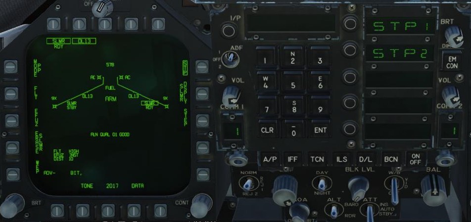
Select the pushbutton next to “STP1” on the UFC to set STP 1.
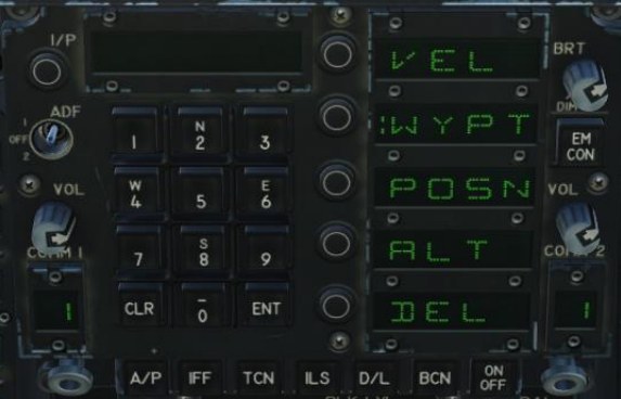
VEL. Specifies the velocity the missile should achieve upon reaching the STP, in knots.
WYPT. Sets the STP location to a waypoint. Enter the waypoint number and press ENT.
POSN. Sets the STP location to a latitude/longitude or an MGRS grid.
ALT. Sets the altitude the missile should achieve upon reaching the STP, in feet.
DEL. Deletes this STP. Any successive STPs will be shifted up.
After creating STP1, “STP2” will appear on the UFC list, allowing you to add a second STP if you wish.
AWW-13 Datalink Format
SLAM-ER datalink video can be set to activate a certain distance from the target in the same manner as the SLAM. To pair the SLAM-ER with the AWW-13 Datalink Pod, select both the SLMR and DL13 options from the Stores format. Press the pushbutton labeled “WPN” and select a SLAM-ER from the list to pair the Datalink Pod to it. You will then see the combined SLAM-ER + AWW-13 video format:
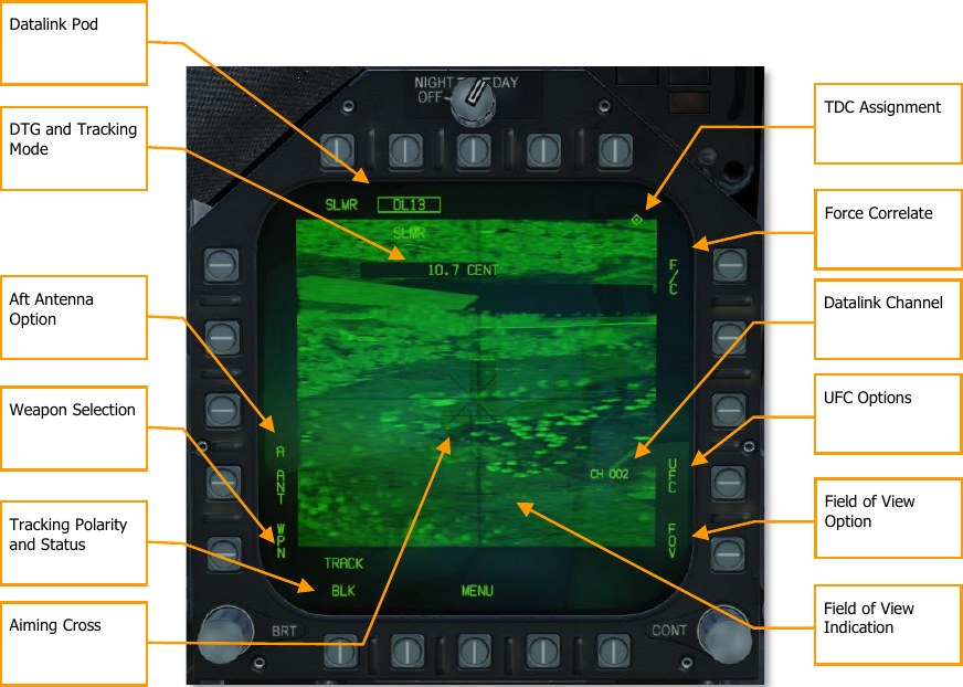
Datalink Pod. Boxed when the AWW-13 is selected as the active Stores sub-page.
DTG and Tracking Mode. Displays the distance to the target in nautical miles and the seeker tracking mode: “CENT” for centroid tracking and “F/C” for forced correlation. Distance to go is not displayed if the SLAM-ER was not launched with a target waypoint.
Aft Antenna. When boxed, the AWW-13 will use its aft antenna instead of its forward antenna. If you lose signal as you turn away from the missile, use the aft antenna.
Weapon Selection. Pressing this PB will allow you to select which weapon to link the AWW-13 to (if you have multiple SLAM-ERs loaded).
Tracking Polarity and Status. Cycles through centroid tracking polarity options. Displays “BLK” when tracking dark objects and “WHT” when tracking bright objects. “TRACK” is displayed when the SLAM-ER is tracking an object.
Aiming Cross. This cross represents the aimpoint of the missile. To slew the aiming cross, hold down the TDC. The image will freeze. While holding down the TDC, use the TDC to reposition the aiming cross to a new location, and release the TDC. The missile will attempt a new track and steer to the new aimpoint.
TDC Assignment. Shown when TDC is assigned to this display. TDC must be assigned to the SLAM- ER/AWW-13 video display to move the aiming cross.
Force Correlate. Cycles between centroid tracking and forced correlation. Centroid tracking attempts to track bright or dark shapes in the image and is more effective against moving vehicles. Forced correlation attempts to track part of an image and is more effective when pinpointing part of a larger structure.
Datalink Channel. Displays the radio channel that the AWW-13 is tuned to. Each missile is assigned a datalink channel based on its station number (e.g., the SLAM-ER loaded at station 2 will transmit over datalink channel 002). Pressing the adjacent PB (PB 14) allows you to specify which channel to tune the AWW-13 to using the UFC.
UFC Options. Pressing this PB displays options on the UFC (see below).
Field of View Option. Pressing this PB cycles between wide and narrow field of view.
Field of View Indication. The square brackets indicate the extent of the narrow field of view. The horizontal lines indicate depression from boresight and are spaced 5° apart.
AGM-62 Walleye II ER/DL with AWW-13 Datalink Pod
The AGM-62 Walleye II ER/DL (Guided Weapon Mk. 5, nicknamed “Fat Albert”) is an air-to-surface, homing glide bomb that incorporates television guidance. It has a 2,000-pound warhead with a maximum glide range of approximately 40 miles. Using HOTAS controls, the pilot can slew the seeker to have it lock on to a target with enough visual contrast. The seeker will then self-track the target even after weapon release. Using the AN/AWW-13 datalink pod, video from the television seeker can then be displayed on the Walleye format page. Using the datalink, the pilot may redirect the bomb to a different target while in flight. The ER/DL in the name indicates Extended Range / Datalink.
The Walleye is designed to attack large, static targets like buildings and bridges, and it can only be mounted on stations 2 and 8 as singles on BRU-32/A bomb racks.
The AN/AWW-13 Advanced Datalink Pod is used to communicate with the Walleye II ER/DL. It allows for retargeting of the weapon after it has been launched by transmitting and receiving post-launch slew and lock-on commands. The AN/AWW-13 provides man-in-the-loop guidance.
The AN/AWW-13 datalink pod can be held on stations 2, 3, 5, 7, and 8.
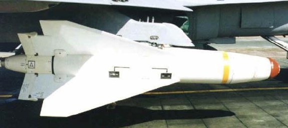
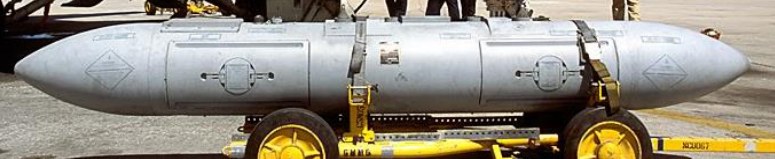
Walleye SMS Page
Because of the possible combination of loading Walleyes and the AN/AWW-13 datalink pod, there are three possible format pages. These formats replace the standard wingform format when selected.
- Only datalink pod
- Only Walleye
- Both datalink pod and Walleye
When both Walleye and the datalink pod are selected, only the top 80% of the displays has video with stroke symbology over the entire display.
AN/AWW-13 Datalink Pod Only Selected
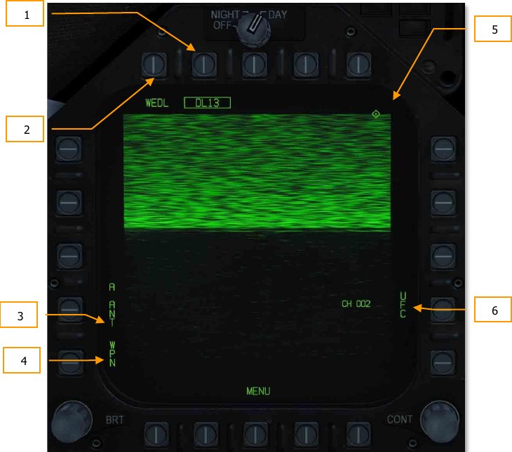
When the datalink pod is selected and a Walleye is not, the top 80% of the display is static because the datalink pod has not been linked to a Walleye seeker. Elements of the datalink only page include:
- Datalink Pod Selection Option. If a datalink pod is loaded, this option allows selection of the pod. This is indicated as DL13 for the AN/AWW-13 pod.
- Weapon Selection Status. An indication of weapon selection status is provided which is like that provided in the Stores format. When an A/G release ready condition exists, RDY is displayed beneath the weapon selection box.
- Pod Antenna Option. The A ANT option selects the aft antenna of the datalink pod. It is boxed when selected. The selection allows forward and aft antenna control of the datalink pod. This can be useful when self-guiding (aft antenna) or potentially guiding for another aircraft (forward antenna).
- Weapon Selection. The Weapon option links the datalink pod to the selected datalink capable weapon. When linked, the option is boxed.
- TDC Assignment Indication. This diamond indicates that the TDC is assigned to the display. To slew the seeker, the TDC must be assigned to the weapon video page.
- UFC Pod Channel Selection Option. This option is used to select one of the two pre-set pod datalink channels, channel 2 if the Walleye is on station 2, or channel 8 if the Walleye is on station 8. Pressing PB 14 displays CHNL on the top Open Select Window on the UFC. Upon colonizing the window, the channel is entered using the keypad and ENT is pressed. If a valid channel is entered (2 or 8), the channel number is listed after CH on the datalink format (002 or 008).
Walleye Only Selected
When a Walleye has been selected but the datalink pod has not, the format page provides functionality to conduct a Walleye attack without datalink. In such a situation, the Walleye can be locked to the target before launch, and there would be no seeker video update once launched. In many ways, it behaves like an infrared-guided Maverick.
Elements of the format include:
- Weapon Selection Status. An indication of weapon selection status is provided which is like that provided in the Stores format. When an A/G release ready condition exists, RDY is displayed beneath the weapon selection box. Otherwise, an “X” is displayed through the WEDL acronym.
- Station Select Indication. The Walleye can be carried on stations 2 and 8. The weapon station selected is indicted beneath the weapon selection status. Station 8 is the default priority station. This can be useful when setting up the correct datalink channel.
- Selected Station. Walleye 2 ER/DL is displayed as WEDL.
- Electrical Fuzing Options. The Walleye has two mutually exclusive fuzing options, instantaneous (INST) and delay (DLY). Pushbutton 5 is used to select instantaneous mode and pushbutton 4 is used to select delay mode.
- Caging Retention and Boresight (CRAB). When the Walleye seeker has been slewed off boresight, this option is displayed. Pressing and holding the pushbutton returns the seeker to boresight.
- Station Step (STEP) Option. Pressing the STEP option toggles the selected Walleye station. If less than two Walleye are loaded, this option is removed from the format.
- Video Crosshairs. The Walleye crosshairs are a part of the weapon video and are colored white.
- Missile Axis Position (MAP) Indicator. The MAP indicator is displayed in the weapon video. Its boresight axis is relative to the guidance head position, and therefore provides an indication of the angle of attack when the weapon is in flight. The MAP indicator is not displayed when it is inside the tracking gate (intersection of the crosshairs). The MAP indicator is displayed at one-half size vertically while the guidance head position is being slewed using the datalink (after the weapon has launched).
- Cage/Uncage Status. The caged/uncaged status of the weapon is provided on the format. When the weapon is initially selected, CAGED is displayed. When the cage/uncage button is pressed to allow the seeker to be slewed, UNCAGED is displayed.
- TDC Assignment Indication. This diamond in the top right concern of the format indicates that the TDC is assigned to the display.
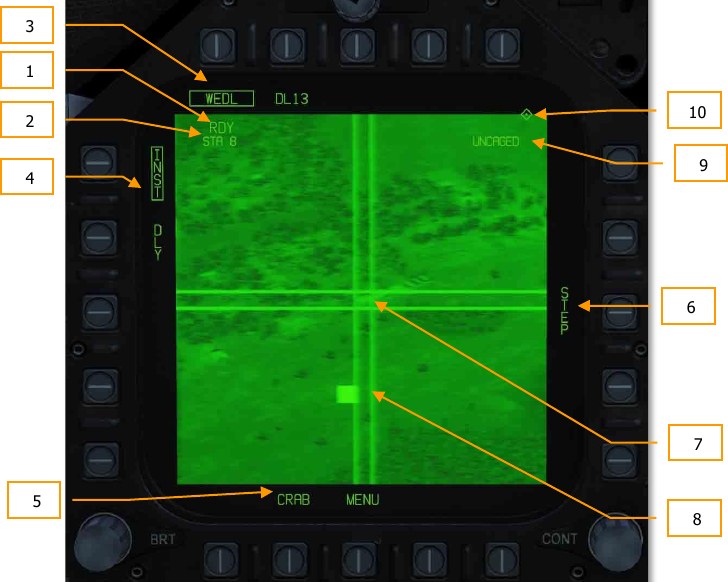
How to Employ the AGM-62 Without Data Link
- Master Arm to ARM and Master Mode switch to A/G
- Select WEDL twice from the SMS page
- Set TDC to the Walleye format page
- Uncage the seeker by pressing Cage/Uncage button or C.
- Slew the crosshair center over a larger target and wait for the seeker to lock on. Indicated by the RDY indication and WE crossed out on the HUD.
- Press the weapons release button LAlt + Space Bar to release the weapon.
Walleye and Datalink Pod Both Selected
The Walleye is most effective when paired with the datalink pod. To pair the two systems:
- Select (box) both the Walleye and datalink pod. This will show the combined Walleye / datalink pod format.
- From pushbutton 1, select WPN (weapon). This informs the datalink pod that it is to be paired with a datalink-capable weapon. Available datalink weapons will now be listed as options for pushbuttons 1 to 4. Walleye (WEDL) will appear on pushbutton 5.
- From pushbutton 5, select WEDL to pair the Walleye and datalink pod. If successful, WEDL will appear below DL13 at pushbutton 8.
Note
if you are not then receiving seeker video, you probably need to set the datalink to the other channel (either channel 2 or 8).
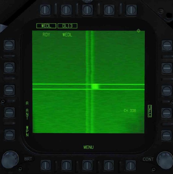
Walleye HUD
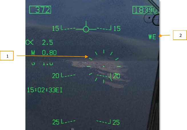
The Walleye HUD consists of the following elements:
- Walleye Reticle. This reticle that duplicates the AG rocket and gun reticle, is positioned 3° below the waterline by default. As the Walleye seeker is slewed, this reticle will reflect seeker slew. In the center of the reticle is an aiming pipper.
- Weapon Name. Walleye II is displayed as WE.