Pilot Cockpit Overview
The Pilot’s primary task is to facilitate the Copilot/Gunner’s ability to operate the aircraft sensors and weapon systems. The Pilot maintains awareness of the aircrew’s surroundings and the tactical situation; and maneuvers the aircraft as necessary to ensure the Copilot/Gunner (CPG) can perform unimpeded sensor scans or employ weapon systems.
The Pilot’s secondary task is to maintain security of the aircraft and aircrew. As the CPG will often be focused inside the cockpit while operating the aircraft sensors, weapons, and radios, the Pilot maintains a “heads-out” focus as much as possible. The Pilot remains on the look-out within the immediate vicinity around the aircraft and is ready to employ the Area Weapon System (AWS) against close-in threats to protect the aircraft or other team members if necessary.
When equipped with the mast-mounted Fire Control Radar (FCR), the Pilot can use the FCR to assist the CPG in the targeting process by directing the CPG to specific areas within which to perform TADS sensor scans, or even hand over individual targets to the CPG for engagement. Alternatively, the Pilot can use the FCR to autonomously detect, acquire and engage enemy targets with any of the aircraft’s three weapon systems.
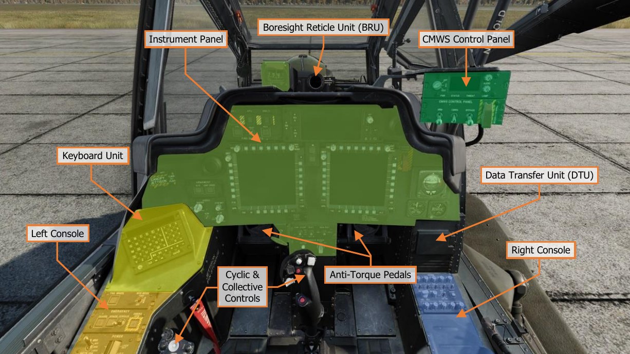
It is important to have a general understanding of where the various controls are located. To help locate items more easily, the cockpit has been delineated into five primary areas: Instrument Panel, the Keyboard Unit (KU), Left Console, Right Console, and the CMWS Control Panel.
Each text box above may be selected to jump to a more detailed description of that instrument panel or console, to include the Cyclic & Collective Controls. Selecting the image of the instrument panel or console will return the manual back to this page.
The CMWS Control Panel is described in the Aircraft Survivability Equipment (ASE) chapter. //link
Instrument Panel
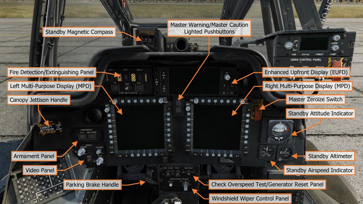
Each text box above may be selected to jump to a more detailed description of that instrument or panel. Selecting the image of the instrument or panel will return the manual back to this page.
The Enhanced Upfront Display (EUFD) and Multi-Function Display (MPD) are described in dedicated sections later in this chapter.
Standby Magnetic Compass
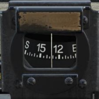
The standby magnetic compass is used by the Pilot for heading reference when there has been a failure of primary power, or the navigation system has become unreliable.
Due to magnetic variances and other inaccuracies during normal flight maneuvers, the standby magnetic compass should not be relied upon for precise heading or navigation information. The aircraft should immediately be recovered to a suitable friendly location. Visual landmarks may be used to maintain awareness of aircraft position and aid in navigation back to maintenance facilities or friendly-controlled areas.
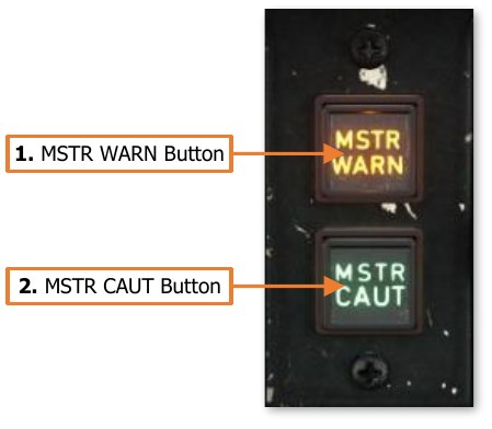
Master Warning/Master Caution Lighted Pushbuttons
The Master Warning/Master Caution lighted pushbuttons alerts the Pilot to observe the EUFD WCA area for warning and caution messages indicating conditions that require their immediate attention.
-
MSTR WARN Button. Acknowledges the MASTER WARNING condition. Extinguishes the MSTR WARN light in the Pilot crewstation and ceases the corresponding voice warning message in both crewstations.
- MSTR WARN Light. Flashes to alert the Pilot to a WARNING message displayed on the EUFD.
-
MSTR WARN Button. Acknowledges the MASTER CAUTION condition. Extinguishes the MSTR CAUT light and ceases the corresponding caution audio tone in the Pilot crewstation.
- MSTR CAUT Light. Illuminates to alert the Pilot to a CAUTION message displayed on the EUFD.
Fire Detection/Extinguishing Panel
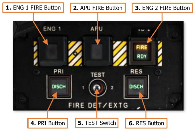
The FIRE DET/EXTG Panel controls the fire detection and suppression equipment. It consists of three pushbutton warning lights, with covers, that illuminate when a fire is detected and two pushbuttons that discharge extinguishing agents into the selected component.
Fire detection sensors are present in each engine nacelle, the APU compartment, and the aft deck area near the transmission accessory gearbox. However, the Halon extinguishing agent can only be discharged into either engine nacelle or the APU compartment.
-
ENG 1 Button. The ENG 1 FIRE button is used to indicate when a fire is detected within the left engine nacelle and to arm the fire extinguishing system for discharge into the left engine nacelle.
-
FIRE Light. The yellow FIRE light will illuminate at any time a fire is detected within the left engine nacelle, and will extinguish when a fire is no longer detected.
-
RDY Light. The green RDY light will illuminate when the ENG 1 FIRE button has been pressed in either crewstation. When pressed, the following occurs:
-
Fuel flow to engine 1 is shut off, however the engine will continue to operate until the remaining fuel within the fuel lines and engine fuel manifold is consumed.
-
The fire extinguishing system is armed.
-
Bleed air from engine 1 is shut off.
-
The MSTR WARN light is acknowledged and the “ENGINE 1 FIRE” voice warning message will cease.
-
-
Once armed, only the crewstation within which the ENG 1 FIRE button was pressed can dis-arm it and restore the systems to their normal operating conditions.
-
-
APU Button. The APU FIRE button is used to indicate when a fire is detected within the APU compartment and to arm the fire extinguishing system for discharge into the APU compartment.
-
FIRE Light. The yellow FIRE light will illuminate at any time a fire is detected within the APU compartment, and will extinguish when a fire is no longer detected.
-
RDY Light. The green RDY light will illuminate when the APU FIRE button has been pressed in either crewstation. When pressed, the following occurs:
-
Fuel flow to APU is shut off, however the APU will continue to operate until the remaining fuel within the fuel lines and APU fuel system is consumed.
-
The fire extinguishing system is armed.
-
Bleed air from the APU is shut off.
-
The MSTR WARN light is acknowledged and the “APU FIRE” voice warning message will cease.
-
-
Once armed, only the crewstation within which the APU FIRE button was pressed can dis-arm it and restore the systems to their normal operating conditions.
-
-
ENG 2 Button. The ENG 2 FIRE button is used to indicate when a fire is detected within the right engine nacelle and to arm the fire extinguishing system for discharge into the right engine nacelle.
-
FIRE Light. The yellow FIRE light will illuminate at any time a fire is detected within the right engine nacelle, and will extinguish when a fire is no longer detected.
-
RDY Light. The green RDY light will illuminate when the ENG 1 FIRE button has been pressed in either crewstation. When pressed, the following occurs:
-
Fuel flow to engine 2 is shut off, however the engine will continue to operate until the remaining fuel within the fuel lines and engine fuel manifold is consumed.
-
The fire extinguishing system is armed.
-
Bleed air from engine 2 is shut off.
-
The MSTR WARN light is acknowledged and the “ENGINE 2 FIRE” voice warning message will cease.
-
-
Once armed, only the crewstation within which the ENG 2 FIRE button was pressed can dis-arm it and restore the systems to their normal operating conditions.
-
-
PRI Button. Pressing this button will discharge the Primary fire extinguishing bottle into the compartment selected using the ENG 1, ENG 2, or APU pushbuttons above.
- DISCH Light. Illuminates when the Primary extinguisher bottle is armed and available for use. When the Primary bottle is discharged, the light will extinguish; or if the fire extinguishing system is disarmed by de-selecting the ENG 1, ENG 2, or APU pushbuttons above.
-
Test Switch. Pressing this switch to the TEST 1 or TEST 2 positions will test the fire detection circuits. When released, the switch is spring-loaded back to the center position.
-
TEST 1. Tests fire detection circuit 1. A successful test is indicated by the following:
-
All three FIRE lights on the ENG 1, ENG 2, and APU pushbuttons are illuminated in both crewstations.
-
The MSTR WARN lighted pushbutton will be illuminated in both crewstations.
-
The AFT DECK FIRE warning message will be displayed on the EUFD.
-
“AFT DECK FIRE”, “ENGINE 1 FIRE”, “ENG 2 FIRE”, “APU FIRE” voice warning messages will be heard in sequence.
-
-
TEST 2. Tests fire detection circuit 2. A successful test is indicated by the same items as the TEST 1 position, with the addition of the following:
- Both DISCH lights on the PRI and RES pushbuttons are illuminated in both crewstations.
-
-
RES Button. Pressing this button will discharge the Reserve fire extinguishing bottle into the compartment selected using the ENG 1, ENG 2, or APU pushbuttons above.
- DISCH Light. Illuminates when the Reserve extinguisher bottle is armed and available for use. When the Reserve bottle is discharged, the light will extinguish; or if the fire extinguishing system is disarmed by de-selecting the ENG 1, ENG 2, or APU pushbuttons above.
Armament Panel
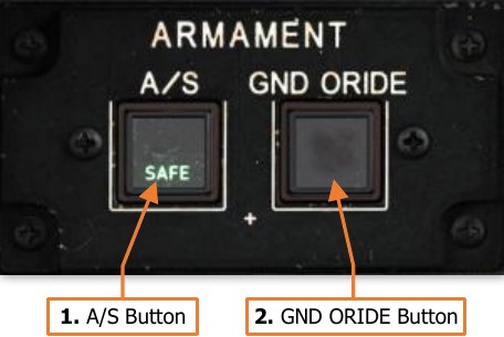
The Armament Panel controls the master arm state of the aircraft. Each button is common to both crewstations, in that pressing a button in one crewstation will change the state of the button in the other crewstation accordingly.
-
A/S Button. Pressing this button toggles the master arm state between ARM and SAFE when the aircraft is not weight- on-wheels, or any time the Ground Override is ON.
-
ARM Light. Indicates the aircraft is Armed.
-
Weapons may be fired from the aircraft.
-
The laser rangefinder/designator may be fired.
-
-
SAFE Light. Indicates the aircraft is Safe.
-
Weapons are inhibited from firing.
-
The laser rangefinder/designator is inhibited from firing.
-
-
-
GND ORIDE Button. Pressing this button enables/disables the Ground Override. The Ground Override state will have no effect on aircraft systems when airborne.
-
ON Light. Indicates the Ground Override is enabled. When on the ground (weight-on-wheels), the following inhibits are affected:
-
The A/S button may be toggled to the ARM state. Disabling the Ground Override will automatically set the A/S button to the SAFE state.
-
Weapon systems may be actioned. Disabling the Ground Override will automatically de-action any actioned weapon systems.
-
FCR emissions are permitted. Disabling the Ground Override will automatically cease any FCR emissions.
-
The Chaff dispenser may be armed. Disabling the Ground Override will automatically set the Chaff state to SAFE.
-
-
Video Panel
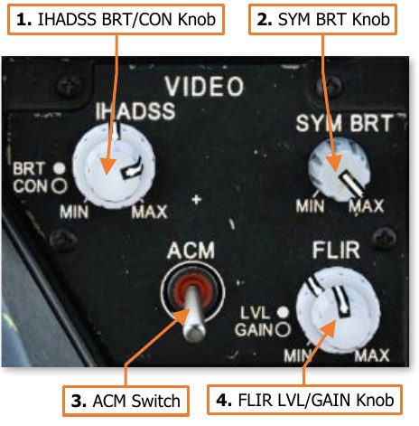
The Video Panel controls the brightness and display of sensor video.
-
IHADSS BRT/CON Knob. Two concentric knobs that controls the brightness and contrast of the Helmet Display Unit (HDU). The outer knob controls video brightness and the inner knob controls video contrast.
-
SYM BRT Knob. Controls the brightness of the IHADSS symbology displayed on the HDU independently of the video underlay.
-
ACM Switch. When on, FLIR gain and level is controlled automatically. When off, the FLIR knob is enabled. (N/I)
-
FLIR LVL/GAIN Knob. Two concentric knobs that control the display of FLIR video from the PNVS or TADS. The outer knob controls level and the inner knob controls gain.
Canopy Jettison Handle
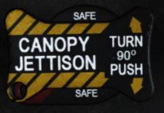
The Canopy Jettison handle can be used to aid in emergency egress from the aircraft. When initiated, the canopy side panels on either side of each crewstation will be explosively jettisoned from the canopy frame. Either crewmember can initiate the canopy jettison process, as can rescue crews via an external jettison handle. (N/I)
Each of the three Canopy Jettison handles are physically locked in place via a safety pin, which are stowed prior to flight. A stowage slot is present in each crewstation for storing the safety pins during flight.
Master Zeroize Switch

The guarded Master Zeroize switch erases all sensitive data onboard the aircraft in the event the aircraft is forced down in a hostile area. (N/I)
Standby Attitude Indicator
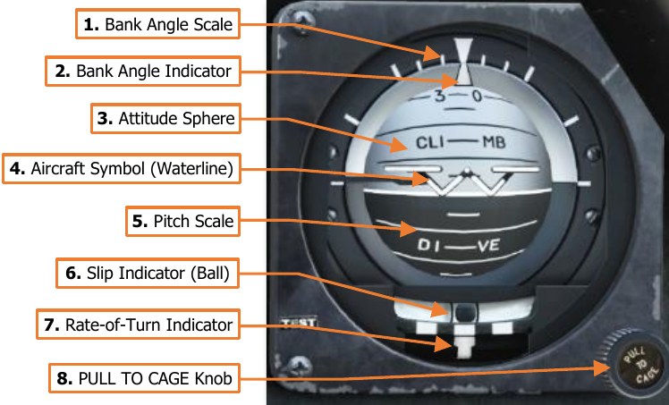
The standby attitude indicator is a self- contained attitude indicator that displays ±85° of aircraft pitch and 360° of aircraft roll. The indicator is used by the Pilot for attitude reference when there has been a failure of primary power, or the flight reference system has become unreliable.
The attitude indicator can develop errors during aggressive maneuvers, which may require it to be caged in flight using the PULL TO CAGE knob.
A yellow OFF warning flag will appear when the indicator is caged, or electrical power to the attitude indicator has been lost.
-
Bank Angle Scale. Indicates the bank angle when used in conjunction with the Bank Angle Indicator. A white triangular bank angle index is set at 0° of bank. Major tick marks are placed at 30°, 60° and 90° angles of bank. Minor tick marks are placed at 10° and 20° angles of bank.
-
Bank Angle Indicator. Indicates bank angle relative to the horizon. When the indicator is aligned with the fixed triangular bank angle index, the aircraft is in a level attitude.
-
Attitude Sphere. Rotates within the indicator to indicate pitch and roll attitude throughout most orientations of flight, in relation to the Aircraft Symbol. The white hemisphere indicates the aircraft nose is pointed above the horizon toward the sky, in a climb. The black hemisphere indicates the aircraft nose is pointed below the horizon toward the ground, in a dive.
-
Aircraft Symbol (Waterline). Provides a fixed attitude reference of the aircraft nose around which the Attitude Sphere rotates. The vertical alignment of the symbol can be manually adjusted by rotating the PULL TO CAGE knob.
-
Pitch Scale. Provides an attitude reference scale of aircraft pitch in relation to the Aircraft Symbol. Major tick marks are placed at every 10° of pitch and minor tick marks are placed at every 5° of pitch.
-
Slip Indicator (Ball). Indicates whether the aircraft is in coordinated flight. With the ball centered between the two black marks, the aircraft is in coordinated flight, which minimizes drag. If the ball is left of center, applying left pedal will adjust tail rotor thrust to bring the aircraft back into coordinated flight. Likewise, if the ball is right of center, applying right pedal will adjust tail rotor thrust to bring the aircraft back into coordinated flight.
-
Rate-of-Turn Indicator. Indicates the aircraft rate of turn, with the lower white bar moving left and right to indicate an increased turn rate in that direction. One bar width equates to 1° to 1.2° per second turn rate. If the lower white bar is aligned with the upper white bar in the center, the aircraft is not turning. If the lower white bar is aligned with the upper white bars on the left or right, the aircraft is in a standard rate, 3° per second turn. If the lower white bar is centered between two of the upper white bars, the aircraft is in a half standard rate turn.
-
PULL TO CAGE Knob. Cages the attitude indicator and is used to adjust the relative pitch of the Aircraft Symbol in relation to the Attitude Sphere. When the knob is pulled outward, the Attitude Sphere is caged to a level attitude orientation regardless of the aircraft’s actual attitude, causing the OFF warning flag to appear. When pulled outward and rotated fully clockwise, the attitude indicator is locked in the caged position.
Standby Airspeed Indicator
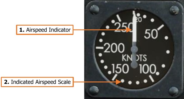
The standby airspeed indicator is used by the Pilot for airspeed reference when there has been a failure of primary power, or the flight reference system has become unreliable. The indicator is pneumatically operated by the right pitot probe.
-
Airspeed Indicator. Indicates indicated airspeed along the Indicated Airspeed Scale.
-
Indicated Airspeed Scale. The outer scale of the instrument, from 0 to 250 knots. Tick marks are set at 50-knot increments, and dots are set at 10-knot increments starting at 20 knots.
Standby Altimeter
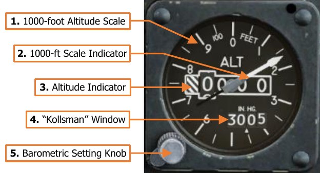
The standby altimeter is used by the Pilot for barometric altitude reference when there has been a failure of primary power, or the flight reference system has become unreliable. The altimeter is pneumatically operated by the static pressure system.
-
1000-foot Altitude Scale. Each major tick mark corresponds with 100-foot increments, with minor tick marks corresponding to 50-foot increments.
-
1000-foot Scale Indicator. Indicates the aircraft altitude on the outer 1000-foot scale.
-
Altitude Indicator. Indicates the current barometric altitude in 1000-foot increments from 0 feet to 20,000 feet.
-
“Kollsman” Window. Indicates current altimeter setting correction in inches of mercury (in/Hg). The altimeter setting on the AH-64D is designed to be used in conjunction with QNH barometric altimeter settings to calibrate the altimeter to altitudes above mean sea level (MSL).
-
Barometric Setting Knob. Sets altimeter setting correction as displayed in the “Kollsman” Window.
Check Overspeed Test/Generator Reset Panel
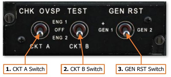
Tests engine overspeed circuits and provides a means to reset the generators if the MPDs are non-functional following a power failure.
-
CKT A Switch. Tests the overspeed protection Circuit A for each engine.
-
ENG 1. Not implemented.
-
OFF. The switch is spring-loaded to this position.
-
ENG 2. Not implemented.
-
-
CKT B Switch. Tests the overspeed protection Circuit B for each engine.
-
ENG 1. Not implemented.
-
OFF. The switch is spring-loaded to this position.
-
ENG 2. Not implemented.
-
-
GEN RST Switch. Performs a reset of either generator in the case of a power failure.
-
GEN 1. Resets Generator 1.
-
GEN 2. Resets Generator 2.
-
Windshield Wiper Control Panel
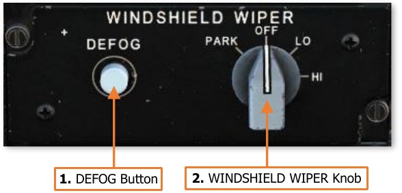
Controls the external windshield wipers and canopy defog functions.
-
DEFOG Button. Directs hot air mixed with ambient air from the cockpit against the canopy side panels to remove fogging. (N/I)
-
WINDSHIELD WIPER Knob. Sets the speed for the windshield wiper or returns the wiper to the PARK position.
-
PARK. Holding the knob in this position will move the windshield wiper to its designated parking location. When released, the knob will be spring-loaded to the OFF position.
-
OFF. Powers off the windshield wiper at its current position.
-
LO. Powers the windshield wiper and sets the motion to low speed.
-
HI. Powers the windshield wiper and sets the motion to high speed.
-
Parking Brake Handle
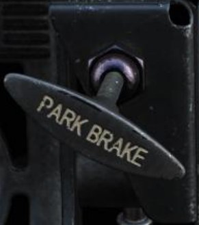
The PARK BRAKE handle can be used by the Pilot to set the wheel brakes without needing to continuously apply pressure to the anti-torque pedals themselves. To set the brakes using this method, the brakes are engaged by applying pressure to the anti-torque pedals in either crewstation, and the Pilot then pulls the PARK BRAKE handle out. The pressure on the anti-torque pedals is then released.
To release the brakes after they have been set using the PARK BRAKE handle, either crewmember may simply apply brake pressure using the anti-torque pedals, and the Parking Brake handle will snap inward.
Note that the PARK BRAKE handle can be pulled and locked in the outward position without applying the wheel brakes, and therefore the outward position of the handle does not directly correlate to the brakes being set. However, if the PARK BRAKE handle is in the forward position, the brakes are indeed released.
Keyboard Unit
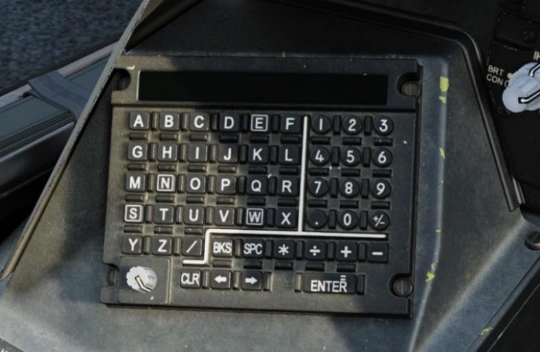
5The Keyboard Unit (KU) is used by the crewmembers to input data into the aircraft computers, perform arithmetic functions, or be used as a scratchpad to temporarily record data for a brief time.
Each Keyboard Unit is independently operated by either crewmember, and data is only entered and utilized by the onboard computers when a data prompt is present on the KU display itself.
The N, E, S and W keys are boxed for easy recognition if coordinates are to be input using Latitude and Longitude.
Data Entry and Arithmetic Functions
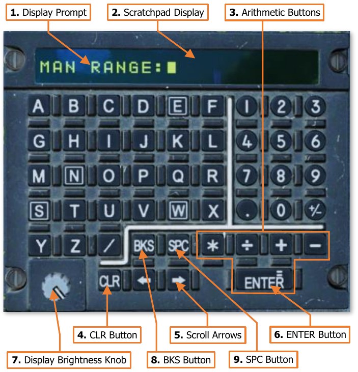
The KU uses an “overtype” method of data entry, in that any data underneath the flashing cursor will be overwritten by the next character entered, and each subsequent character to the right of the cursor will be continuously overwritten as more characters are entered.
-
Display Prompt. Indicates the type of data that will be input if accepted by the avionics. Pressing an MPD pushbutton associated with a data entry symbol > will show the corresponding prompt on the KU followed by a colon. The desired data can then be input into the scratchpad.
-
Scratchpad Display. The maximum number of characters that can be displayed on the KU scratchpad itself is 22, but the scroll buttons can be used to move the cursor left or right in a continuous scrolling fashion if the data entry exceeds the 22 characters on the display.
-
Arithmetic Buttons. If a display prompt is not present on the scratchpad display, basic arithmetic functions may be performed using these keys. To perform basic arithmetic, enter a number, followed by either the * (multiply), ÷ (divide), + (add), or - (subtract) keys. Enter another number and press Enter (equal). The resultant value will display on the scratch pad.
-
CLR Button. Removes all data entered on the scratchpad but will not remove or cancel a display prompt if present.
-
Scroll Arrows. Moves the cursor position left or right on the display to set the data entry point over existing characters.
-
ENTER Button. Used to accept a data input to an MPD data entry prompt. If data input is invalid, the characters on the scratchpad display will flash, and the data will need to be edited before it can be accepted into the MPD data prompt.
-
Display Brightness Knob. Adjusts the brightness of the KU scratchpad display.
-
BKS Button. Removes the character to the left of the cursor and shifts the cursor to the left, along with any characters underneath or to the right of the cursor.
-
SPC Button. Places a blank character space at the cursor position.
Left Console
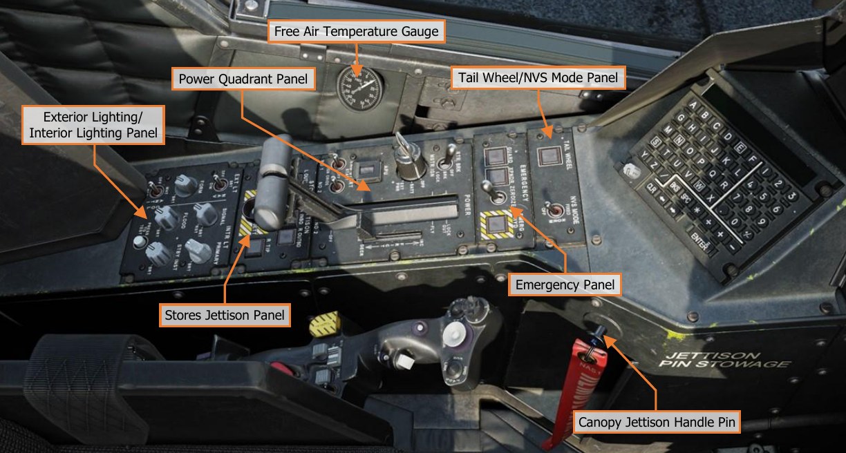
Each text box above may be selected to jump to a more detailed description of that panel. Selecting the image of the panel will return the manual back to this page.
Tail Wheel/NVS Mode Panel
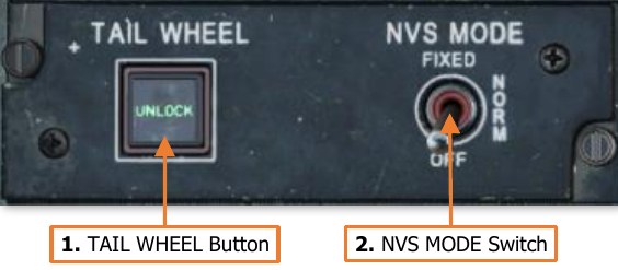
Controls the tail wheel locking mechanism and the operating mode of the crewstation’s Night Vision System.
-
TAIL WHEEL Button. Toggles the commanded state of the tail wheel locking mechanism between locked and unlocked.
- UNLOCK Light. Illuminates to indicate when the tail wheel is unlocked, regardless of the commanded state of the locking mechanism.
-
NVS MODE Switch. Sets the operating mode of the Night Vision System within the crewstation. The default NVS sensor selections are the PNVS in the Pilot crewstation and the TADS in the CPG crewstation, unless the NVS Select Switch on the Collective Flight Grip has been used to swap the NVS sensor selections.
-
FIXED. Activates the selected NVS sensor and slaves it to the fixed forward position (0° in azimuth and -4.9° in elevation). If the selected NVS sensor is the PNVS, it will be un-stowed. If the selected NVS sensor is TADS, it will switch to FLIR in Wide field-of-view, regardless of the TEDAC switch settings.
-
NORM. Activates the selected NVS sensor and slaves it to the crewmember’s IHADSS line-of-sight. If the selected NVS sensor is the PNVS, it will be un-stowed. If the selected NVS sensor is TADS, it will switch to FLIR in Wide field-of-view, regardless of the TEDAC switch settings.
-
OFF. Deactivates the selected NVS sensor and stows it. The PNVS will return to the stowed position and the TADS will stow in the fixed forward position (0° in azimuth and -4.9° in elevation).
-
Emergency Panel
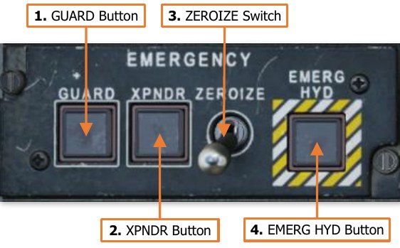
The Emergency Panel provides a singular location for the crewmember to perform miscellaneous emergency actions, without requiring navigation through MPD pages to access the associated functions. (N/I)
-
GUARD Button. Tunes the UHF radio to the GUARD frequency of 243.000 MHz. The frequency in the Primary slot of the UHF radio will be moved to the Standby slot, and GUARD will be displayed as the frequency callsign. Pressing this button when it is already set to ON will return the previous UHF frequency to the Primary slot and place the GUARD frequency in the Standby slot.
- ON Light. Illuminates to indicate that the GUARD button has been pressed in either crewstation.
-
XPNDR Button. Sets the transponder Mode 3/A code to 7700 to indicate the aircraft is experiencing an in- flight emergency. If the transponder is in STBY, it will automatically be set to NORM, and EUFD transponder information will indicate a status of “7700 EMER”. Pressing this button when it is already set to ON will return the transponder to the NORM status, but the Mode 3/A code will need to be manually changed by either crewmember.
- ON Light. Illuminates to indicate that the XPNDR button has been pressed in either crewstation.
-
ZEROIZE Switch. When set to the forward position, all communications encryption, modem settings, and any TSD points within the navigational database will be erased.
-
EMERG HYD Button. Activates the emergency hydraulics system. This system provides emergency hydraulic pressure to the utility hydraulic system for a very brief period in order to perform an immediate emergency landing.
- ON Light. Illuminates to indicate that the emergency hydraulics has been activated by either crewmember.
Power Quadrant Panel
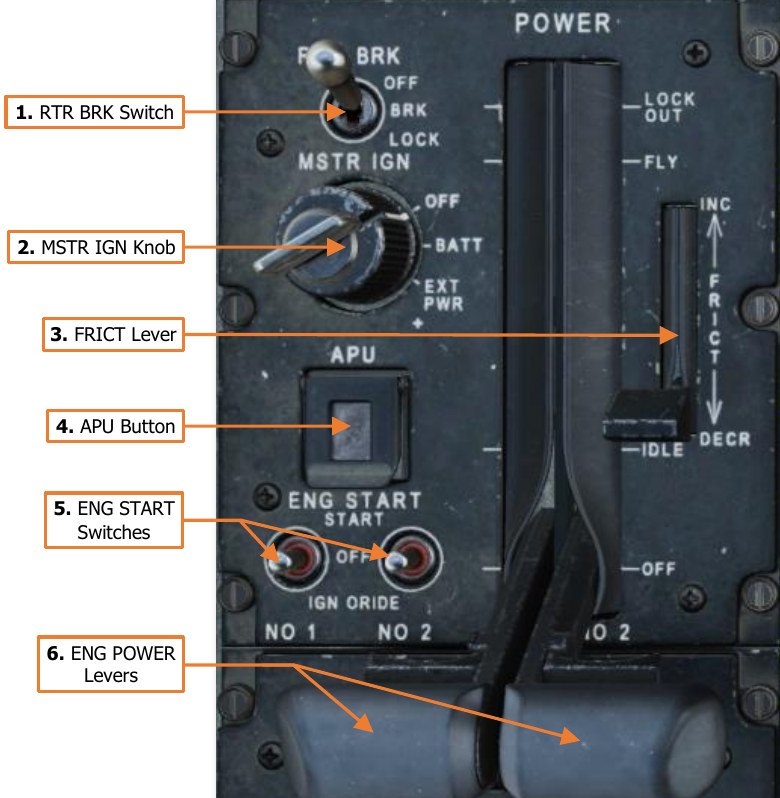
The Pilot’s Power Quadrant includes controls for battery, APU and engine start, and rotor brake operation. The POWER levers manage engine output during normal and manual control operations.
-
RTR BRK Switch. Controls the commanded state of the rotor brake mounted to the accessory gearbox of the main transmission.
-
OFF. The rotor brake is commanded to disengage.
-
BRK. The rotor brake is commanded to engage in a low-pressure state to reduce the time it takes for the rotor system to decelerate to a stop. Used when shutting down in high winds or when on board a naval vessel in rough sea conditions.
-
LOCK. The rotor brake is commanded to engage in a high-pressure state to prevent the rotor from spinning. Used when performing an engine start in high winds or when on board a naval vessel in rough sea conditions. Rotor brake operation is electronically inhibited if either ENG POWER lever is beyond the IDLE position.
-
-
MSTR IGN Knob. Enables battery or external power to the aircraft.
-
OFF. Disconnects the battery from the DC battery bus.
-
BATT. Connects the battery to the DC battery bus. If the aircraft is receiving DC power from the Transformer-Rectifier Units (TRUs), the battery will be set to a charging state, but will automatically provide emergency power to the battery bus if a TRU failure occurs.
-
EXT PWR. Enables external AC and DC power to be supplied via the external power receptacle.
-
-
FRICT Lever. Adjusts the friction resistance when moving the engine power levers. (N/I)
-
APU Button. Intiates the APU automatic start-up and shutdown sequences.
- ON Light. Illuminates to indicate when the APU has successfully started and is operating.
-
ENG START Switches. Controls the pneumatic air starters and ignition systems of each main engine.
-
START. Moving the switch momentarily to this position initiates an automatic start sequence for the respective engine and enables the engine ignitors. The System Processor (SP) will automatically activate the fuel boost pump and open the pneumatic valve to the engine air starter to spool the NG section of the engine. The SP will automatically close the pneumatic valve to disengage the starter when the NG reaches 52% RPM.
-
OFF. Normal position of the ENG START switch after initiating a START sequence or motoring the engine using the IGN ORIDE position.
-
IGN ORIDE. Moving the switch to this position manually opens the pneumatic valve to the engine air starters to spool the NG section of the engine. The System Processor (SP) will not activate the fuel boost pump nor the engine ignition system. The pneumatic air starters will continue to spool the N G section of the engine at ~25% RPM until the ENG START switch is returned to the OFF position, which will close the close the pneumatic valve to disengage the starter. An engine start sequence may be aborted by setting the ENG START switches to the IGN ORIDE position and then to OFF. This will disable the engine ignition system, disengage the engine air starters, and the fuel boost pump will be automatically deactivated by the SP.
-
-
ENG POWER Levers. Controls the fuel flow and control mode of each main engine. Each ENG POWER lever is connected to the corresponding Hydromechanical Unit (HMU) on the engine through the Power Available Spindle (PAS). Each ENG POWER lever includes a detent that prevents the lever from being inadvertantly advanced beyond FLY into the LOCK OUT range, or retarded below IDLE to OFF. A finger-lift detent lever on each ENG POWER lever disengages the mechanical detents.
-
LOCK OUT. Setting the ENG POWER lever to this position will lock out the Digital Electronic Control (DEC) from electronically regulating fuel flow and will set the engine throttle to fully open. This will also disable the NP overspeed protection and TGT limiting functions of the DEC, so the engine throttle will need to be manually controlled using the ENG POWER lever to prevent an overspeed or overtemperature condition. This position is only used during emergency procedures in which the DEC has malfunctioned or failed in some manner, requiring the aircrew to manually control the engine throttle in order to prevent an engine overspeed or overtemperature, or to maintain the rotor RPM (NR) within an acceptable range for flight.
-
FLY. Setting the ENG POWER lever to this position will set the PAS to the FLY position and command the DEC to trim fuel flow to maintain the rotor RPM (NR) at 101%. Each engine will automatically regulate their respective throttle settings to equally balance the torque requirement between each engine (load-sharing).
-
IDLE. Setting the ENG POWER lever to this position will set the PAS to the IDLE position. The DEC will no longer regulate the fuel flow based on rotor RPM (NR) and the load-sharing logic between the engines is disabled. Setting the ENG POWER lever to this position will also reset the DEC from the LOCK OUT condition, returning DEC-related functionality to the respective engine.
-
OFF. Setting the ENG POWER lever to this position will set the PAS to the OFF position, shutting off fuel flow to the engine. When the RTR BRK switch is in the BRK or LOCK positions, the ENG POWER levers will be physically inhibited from advancing beyond the IDLE position.
-
Stores Jettison Panel
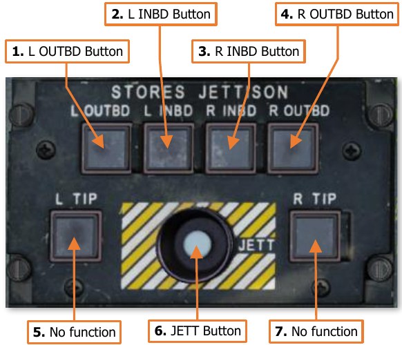
The Stores Jettison panel allows the crewmembers to selectively jettison individual weapon stations in lieu of performing an emergency jettison of all stations at once.
Each weapon station can be armed/disarmed by toggling the corresponding pushbutton on this panel. Each pushbutton includes an ARM light which indicates that that station will be jettisoned when the JETT button is pressed.
Only the crewstation that has armed a weapon station for jettison can disarm it. However, once any stations are armed, either crewmember can initiate the jettison sequence by pressing the JETT button.
-
L OUTBD Button. Arms/disarms the left outboard wing station for jettison.
-
L INBD Button. Arms/disarms the left inboard wing station for jettison.
-
R INBD Button. Arms/disarms the right inboard wing station for jettison.
-
R OUTBD Button. Arms/disarms the right outboard wing station for jettison.
-
L TIP Button. No function.
-
JETT Button. Jettisons any weapon stations that have been selectively armed.
-
R TIP Button. No function.
Exterior Lighting/Interior Lighting Panel
The Exterior Lighting/Interior Lighting panel controls the exterior aircraft lighting and the interior lighting within the Pilot cockpit.
-
NAV Switch. Sets the brightness levels of the engine nacelle-mounted red/green and the tail mounted white navigation lights.
-
BRT. Sets the navigation lights to bright.
-
OFF. Sets the navigation lights to off.
-
DIM. Sets the navigation lights to dim.
-
-
SIGNAL Knob. Adjusts the brightness of the signal lights within the cockpit when set to nighttime brightness levels. This knob will have no function if the signal lights are set to daytime brightness level. Rotating the knob to the RST (Reset) detent will set the signal light brightness scale to nighttime levels
if the PRIMARY knob is not in the OFF position and the FLOOD knob is less than 50%.
-
PRIMARY Knob. Adjusts the brightness of the primary instrument backlighting within the cockpit. Rotating this knob to the OFF position will revert the signal lights to daytime mode.
-
FORM Knob. Adjusts the brightness of the exterior formation lights on the wing tips, tail boom, and vertical stabilizer.
-
FLOOD Knob. Adjusts the brightness of the interior flood lights within the cockpit. Rotating this knob clockwise beyond the 50% setting will revert the signal lights to daytime mode.
-
STBY INST Knob. Adjusts the brightness of the standby instrument illumination within the cockpit.
-
ANTI COLL Switch. Sets the operating mode of the engine nacelle-mounted anti-collision strobe lights.
-
WHT. Sets the anti-collision lights to a white, alternating flash pattern.
-
OFF. Sets the anti-collision lights to off.
-
RED. Sets the anti-collision lights to a red, alternating flash pattern.
-
-
PRESS TO TEST Button. Illuminates all signal lights to verify their function.
Free Air Temperature Gauge
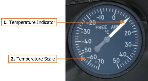
The Free Air temperature gauge indicates the temperature of the external air mass via a probe directly protruding from the gauge itself through the fuselage to the outside of the aircraft.
-
Temperature Indicator. Indicates air temperature in Celsius (°C) as directly measured outside the pilot cockpit.
-
Temperature Scale. Each major tick mark corresponds with 10-degree increments, with minor tick marks corresponding to 2-degree increments.
Right Console
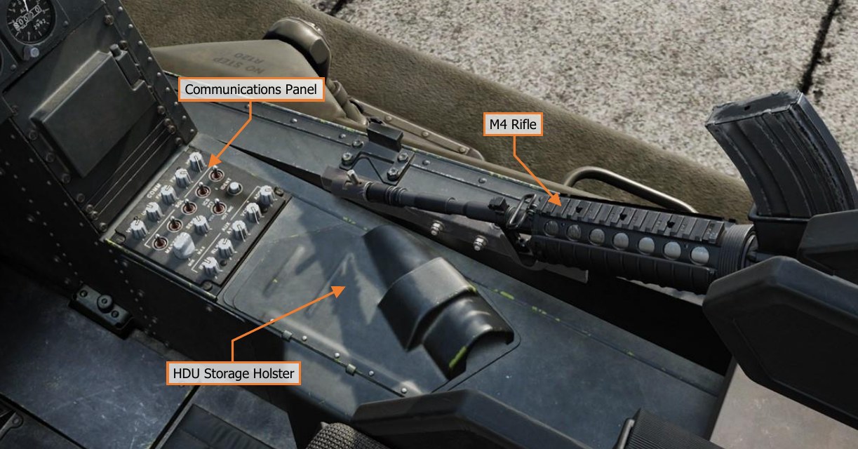
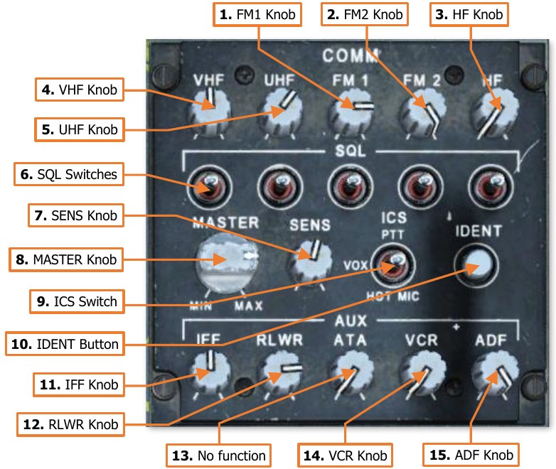
Communications Panel
The Communications panel controls the
volume of the intercom, radios, and
other audio sources within the
crewstation.
-
FM1 Knob. Adjusts the volume of the FM1 radio. Rotating the knob clockwise will increase the volume level; and pulling the knob
outward will mute the audio from the FM1 radio. -
FM2 Knob. Adjusts the volume of
the FM2 radio. Rotating the knob clockwise will increase the volume level; and pulling the knob outward will mute the audio from
the FM2 radio. -
HF Knob. Adjusts the volume of the HF radio. Rotating the knob
clockwise will increase the volume level; and pulling the knob outward will mute the audio from the HF radio. -
VHF Knob. Adjusts the volume of the VHF radio. Rotating the knob clockwise will increase the volume level; and pulling the knob outward will mute the audio from the VHF radio.
-
UHF Knob. Adjusts the volume of the UHF radio. Rotating the knob clockwise will increase the volume level; and pulling the knob outward will mute the audio from the UHF radio.
-
SQL Switches. Momentarily pressing these switches to the forward or aft positions will toggle the squelch function of the corresponding radio.
-
SENS Knob. Adjusts the voice-activation sensitivity when the intercom switch is in the VOX position. Rotating the knob clockwise will increase the sensitivity and lower the voice-activation threshold.
-
MASTER Knob. Adjusts the overall volume level of all audio sources received within the crewmember’s helmet.
-
ICS Switch. Controls the operating mode of the crewmember’s mic on the intercom audio circuit.
-
PTT. The crewmember’s mic will only be activated when the Push-To-Talk switch on the cyclic or the floor button is depressed.
-
VOX. The crewmember’s mic will be activated any time the voice level exceeds the threshold set by the SENS knob, or when the Push-To-Talk switch on the cyclic or the floor button is depressed.
-
HOT MIC. The crewmember’s mic is continuously activated.
-
-
IDENT Button. When pressed, the transponder performs an identification-of-position function. This is used to momentarily highlight the ownship position when replying to non-encrypted transponder interrogations (non-Mode 4 interrogations). (N/I)
-
IFF Knob. Adjusts the volume of the IFF interrogation audio. Rotating the knob clockwise will increase the volume level. (N/I)
-
RLWR Knob. Adjusts the volume of the voice warning messages received from the APR-39/AVR-2 Radar/Laser Warning Receiver system; as well as the Radar Frequency Interferometer (RFI) if the mast- mounted FCR is installed and the RFI is operational. Rotating the knob clockwise will increase the volume level.
-
ATA Knob. No function.
-
VCR Knob. Adjusts the volume of the VCR audio when video playback is enabled. Rotating the knob clockwise will increase the volume level; and pulling the knob outward will mute the audio from the VCR playback. (N/I)
-
ADF Knob. Adjusts the volume of the audio received from the ARN-149 Automatic Direction Finder (ADF). Rotating the knob clockwise will increase the volume level; and pulling the knob outward will mute the audio from the ADF receiver.