AN/ASQ-228 ATFLIR
The Advanced Targeting Forward Looking Infrared (ATFLIR) pod is a slewable electro-optical pod with laser designation, ranging, and searching capability. It is capable of both video and infrared imaging, as well as moving target tracking. The ATFLIR is effective in both the air-to-ground and air- to-air role. The ATFLIR can only be mounted on the left cheek hardpoint, and weighs 424 lbs. The ATFLIR is selected from the PB6 on the TAC page with the Master Mode set to A/G or NAV. The ATFLIR camera is slewed using the TDC, when the TDC is assigned to the DDI displaying the FLIR format. As with other formats, a small diamond appears in the top-right corner of the display when TDC is assigned to that DDI. TDC assignment is done using the Sensor Control Switch on the stick.
The three primary operating modes of the ATFLIR are standby (STBY), air-to-ground (A/G) and air- to-air (A/A). The FLIR format is also available while the ATFLIR is warming up (“not timed out”). The ATFLIR’s sensor suite is mounted on a gimballed platform that can move in two directions. The sensor platform is normally stowed when the power switch is in OFF or STBY, when the landing gear is down, and when the aircraft is stopped on the ground. When airborne and with the ATFLIR active, the sensor platform rotates, exposing the lenses. The sensor platform is free to rotate in two axes but is limited by obscuration from the aircraft or the rest of the pod structure. This is true of the FLIR and CCD video, the laser target designator, and the laser spot tracker. When the sensors are obscured by a part of the aircraft or the pod itself, the sensors are said to be “masked.”
When the laser target designator (LTD) fires, it modulates the laser signal with a pre-coded pulse repetition frequency (PRF). This PRF is coded as a four-digit number, from 1211 to 1688, which is used to distinguish between different simultaneous laser designations made by other aircraft or ground units. Likewise, when the laser spot tracker (LST) searches for a laser, it does so using a specific PRF code, and ignores laser spots with a different code (or unmodulated laser emissions with no code). The code used by the LTD and the one used by the LST need not be the same. Sensor Control Panel
Power to the FLIR, laser target designator (LTD), and laser spot tracker (LST) is done using controls on the Sensor Control Panel.

-
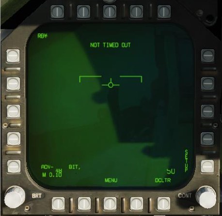
FLIR Power Switch. In OFF, power to the ATFLIR is removed. In STBY, power is applied to the ATFLIR but no video is displayed. In ON, power is applied, and video is displayed. Moving the power switch from OFF to either STBY or ON begins a warm-up period, during which the FLIR format will display NOT TIMED OUT.
-
Laser Target Designator Power Switch. When set to SAFE, the laser target designator will not fire. When set to ARM, the laser target designator will fire when commanded.
-
Laser Spot Tracker Power Switch. Controls power to the laser spot tracker.
ATFLIR Activation
Before the targeting pod can be used, power must be applied. This is done by moving the FLIR Power switch from OFF to either STBY or ON. After doing so, the targeting pod will enter a warm-up period. During this time, the FLIR format will display NOT TIMED OUT:
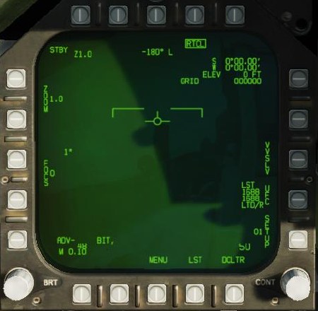
Once the warmup period is complete, if the FLIR Power switch is in STBY, the FLIR format will display STBY in the upper-left corner, and show standby symbology:
If the FLIR Power switch is moved to ON, the ATFLIR will begin displaying video. Initially, video will be slaved to the velocity vector (VVSLV).
Air-to-Ground Mode
The ATFLIR is in air-to-ground mode any time the aircraft master mode is A/G.

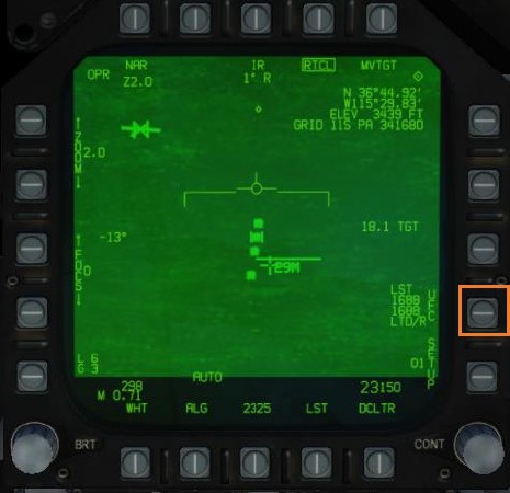
Operating Mode. Displays the current operating mode of the ATFLIR: - -RDY-: Not timed out (ATFLIR is warming up) - STBY: Standby (ATFLIR is powered but in standby mode) - IBIT: Interruptive BIT (ATFLIR is in TEST mode) - OPR: Operating
Field of View. Depressing this PB toggles between WFOV (wide field-of-view), MFOV (medium field- of-view) and NAR (narrow field-of-view). The second line displays the current zoom level within that field of view. Both MFOV and NAR have Z1.0 and Z2.0 levels available, while WFOV only has Z1.0.
Zoom Level. The pushbuttons alter the zoom level within the current field of view. The current zoom level is shown adjacent to the word “ZOOM”. Both MFOV and NAR have Z1.0 and Z2.0 levels available, while WFOV only has Z1.0.
Field of view and zoom together can also be modified using the antenna elevation control on the throttle when TDC is assigned to the FLIR.
TV/IR. Pressing this PB toggles the video display between TV (normal CCD video) and IR (infrared video).
FOV Azimuth/Elevation. These fields indicate the ATFLIR field-of-view’s angle away from boresight. In the image, the ATFLIR is pointing 1° right of boresight and 12° below boresight.
Focus. The pushbuttons alter the focus level of the IR video. The number adjacent the word “FOCUS” is the current focus level. Not implemented.
Polarity. Pressing this PB toggles the infrared video between WHT (white-hot) and BLK (black-hot) polarity. Not shown when TV video is active.
Auto Level & Gain. Pressing this PB toggles auto level and gain on and off. When on, video level and gain is controlled automatically to produce the best image. When off, level and gain is controlled by the pilot. See Manually Controlling Level and Gain, below.
Reticle Toggle. Pressing this PB displays or inhibits the reticle.
Coordinates. This datablock displays the coordinates where the current pod FOV intersects with the ground (i.e., the location under the reticle). Coordinates are displayed as latitude and longitude, then elevation, and then MGRS grid. If the offset reticle is displayed, the coordinates will reference the offset reticle.
VVI Slave. Boxing VVSLV slaves pod LOS to the VVI in the HUD. VVSLV can also be activated by pressing the Undesignate button twice.
Setup Page. Pressing this PB displays additional setup options. The number adjacent the word “SETUP” is the active profile. Currently only profile 01 is available. See SETUP Menu, below.
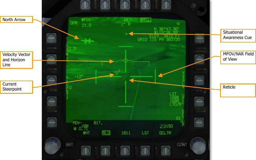
Reticle. The reticle indicates pod LOS. The shape of the reticle depends on the current tracking mode (see Tracking Modes, below).
MFOV/NAR Field of View. In WFOV, the tick marks at the edges of the reticle indicate the MFOV area. In MFOV, the ticks indicate the NAR area. The tick marks are larger in WFOV than they are in MFOV, to indicate the current zoom level. The tick marks are not displayed in NAR.
North Arrow. Indicates the direction of magnetic north. Rendered as four tick marks oriented along the ground plane.
Velocity Vector and Horizon Line. Repeats the velocity vector and horizon line on the HUD. The horizon line flashes if the aircraft enters an unusual attitude.
Current Steerpoint. Indicates the location (including elevation) and number of the active steerpoint.
Situational Awareness Cue. This diamond moves left or right from center to indicate that the pod has a left or right azimuth offset from boresight. The diamond moves up or down to indicate that the pod has an up or down elevation offset from boresight. When boresighted, the diamond is centered laterally and close to the top of the display. The extreme edges of the display roughly correspond to the slew limits of the pod. The diamond is centered vertically on the screen when the pod is pointed straight down.

Tracking Mode. Indicates the current target tracking mode. See Tracking Modes, below. Pressing the SCS in the direction of the FLIR format cycles between designation, SCENE, and AUTO tracking modes. Pressing the Undesignate button activates INR tracking mode.
Tracking Gates. In AUTO track mode, the reticle becomes a pair of tracking gates. The gates expand or contract to enclose the target that was contrast-locked and is being tracked.
Offset Designation Reticle. This reticle is used to make an offset designation (see Offset Designation, below).
Meterstick. The meterstick is rendered as a horizontal line. The number below the meterstick is the length of that line in meters along the ground plane.
Moving Target Indication. “MVTGT” is displayed when tracking a moving target. This field is blank when not tracking a moving target.
Tracking Modes
The ATFLIR is in one of the following tracking modes at any time:
-
INR. This mode is active when the pod is being slewed. It maintains pod orientation relative to the aircraft by using inertial rate data from the aircraft.
-
SCENE. The ATFLIR attempts to track the portion of the image under the reticle. This tracking mode is effective against stationary targets without well-defined edges.
-
INR SCENE. The ATFLIR enters this mode when the pod is slewed while in SCENE mode. The ATFLIR will enter SCENE mode again once slewing is complete.
-
AUTO. The ATFLIR attempts to track an object centroid using a contrast-detecting algorithm. This tracking mode is effective against stationary and moving targets with well- defined edges, either in TV or IR mode.
-
INR AUTO. The ATFLIR enters this mode when the pod is acquiring a target while in AUTO mode. The ATFLIR will enter AUTO mode once acquisition is complete.
-
Designation. Pod LOS is slaved to the designated target or target waypoint.
Initially the ATFLIR will be in designation mode or will be slaved to the VVI if there is no designation. Pressing the SCS in the direction of the FLIR format will cycle between designation, SCENE, and AUTO modes. Pressing the Undesignate button once will return to INR mode, and pressing it twice will slave the pod to the VVI.
In INR and SCENE modes, the pod can be slewed using the TDC. In designation mode, pressing down on the TDC will activate slew and allow the designation to moved. The TDC cannot be moved in AUTO mode, whether or not the pod is tracking a target.
The reticle shape changes depending on the current tracking mode:


Using the LTD/R and LST
The FLIR format has options and indications relevant to laser designation and laser search:

Laser Arm. This field is displayed whenever the LTD/R switch is in ARM.
Time to Release. Displays the estimated time until reaching the weapon release point, in seconds. Post-release, the “REL” text will change to “LASER” and the field will count down until the time the laser begins firing (for LGB attacks). Finally, the text will change to “TTI” and the field will count down the estimated time until impact.
Distance to Target. The range to the tracked target, in nautical miles. Displayed when the ATFLIR is in a track mode and the LTD/R is armed.
Hot Trigger. Boxing this option will cause the laser to fire whenever the trigger is pressed. When the trigger is pressed, the laser will fire for two seconds. When the trigger is held down, the laser will fire continuously.
Laser Spot Tracker. Pressing this PB activates the laser spot tracker. See Using Laser Spot Tracking, below.
Laser Codes. Pressing this PB displays options for setting the LTD/R and LST laser codes on the UFC (see Setting Laser Codes, below). The datablock indicates the selected laser codes for the laser spot tracker and the laser target designator/ranger.
SETUP Menu
Pressing PB 15 (SETUP) will display the setup menu:
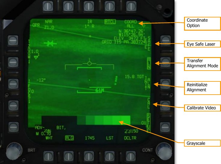
Coordinate Option. Pressing this PB cycles between the display options for the coordinates datablock: ALL (latitude/longitude, elevation, and MGRS), L/L (latitude/longitude and elevation), GRID (elevation and MGRS) and OFF.
Eye Safe Laser. Boxing this option sets the LTD/R laser power to an eye-safe level suitable for training. Not implemented.
Transfer Alignment Mode. When boxed, the primary transfer alignment mode (transfers aircraft position and velocity) is used. When unboxed, the reversionary transfer alignment mode (transfers aircraft position only) is used. Not implemented.
Reinitialize Alignment. Restarts the transfer alignment process. Not implemented.
Grayscale. A static grayscale image. Can be used when manually setting level and gain.
Setting Laser Codes
To set the laser codes for the LTD/R or the LST, press PB 14, labeled “UFC”:
Then, on the UFC, press the OSB adjacent to either LTDC (to set the LTD/R code) or LSTC (to set the LST code):

Finally, enter the laser code and press ENT. The new code will be reflected on the FLIR format.
Designating and Tracking Ground Targets
The ATFLIR will initially be slewed to the designated target, if one has been designated. For example, if you have a waypoint in the vicinity of the target area, or an A/G radar lock in the target area, designating that waypoint or radar lock will cause the ATFLIR to slew to that location. From there, you can assign TDC to the FLIR format, and press down on the TDC to activate slewing. Use the TDC to locate the target and move the designation to it.
Designate mode is an inertial-rates tracking mode, which means the pod is using the aircraft’s inertial data only to track the target, which will incur inaccuracies over time. With the TDC assigned to the FLIR format, press the SCS in the direction of the FLIR format to change to SCENE tracking mode. SCENE mode is suitable for tracking stationary targets.
If you wish to track a moving target, position the reticle just ahead of the moving target and then press the SCS once more to change to AUTO mode. As the vehicle moves into the reticle, the pod will lock onto it and begin tracking it. If the pod was unable to acquire the target, cycle back to INR or SCENE mode, reposition the reticle, and change back to AUTO mode for another attempt.
Once a target has been acquired by the pod, the designation can be used for attacks with laser- guided bombs. See Laser-Guided Bombing for more.
Pressing the Undesignate button will return the pod to INR mode.
Offset Designation
When in AUTO mode with a target acquired, pressing the TDC will show the Offset Designation reticle:
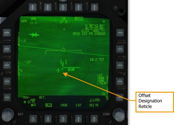
When the Offset Designation reticle is displayed, the coordinates in the top-right datablock reference that reticle instead of the tracked target. You can slew the Offset Designation reticle using the TDC. The Offset Designation reticle always moves relative to the tracked target; it is not ground-stabilized.
Designating Targets Using the Laser
The laser target designator/rangefinder (LTD/R) is a pulsed laser that is automatically aimed along pod line of sight. In the designation role, the laser can provide a guidance solution for laser-guided munitions, both onboard the designating aircraft and from other units; and it can train other platforms’ sensors onto the designated target. In the range-finding role, the laser provides continuous target slant range measurements to the aircraft avionics.
To use the LTD/R, the LTD/R switch on the Sensor Control Panel must be set to ARM. Normally, the laser will fire automatically when designating a target, launching an AGM-65E, or dropping an LGB. Boxing the TRIG option (PB 11) allows the laser to be controlled by the trigger. This is useful when buddy-lasing (designating a target for another aircraft to fire upon).
Using Laser Spot Tracking
The ATFLIR can also detect and track laser signals emitted by other aircraft or ground units, in laser spot track (LST) mode. In this mode, the targeting pod searches for a laser signal by its PRF code. When the laser signal is detected, the pod slews to the target being designated by that laser. Laser spot tracking can by other aircraft or ground units to slew your targeting pod onto their target.
To set the PRF code that the laser spot tracker searches for, press PB 14 (UFC) on the FLIR format. Box PB 17 (labeled LST) to activate LST mode. The display will initially blank:

Once a designation laser is detected, the pod will slew to its location, and “LST” will be displayed at the top of the FLIR format. You can then designate the target or switch to a tracking mode, and LST mode will automatically exit.
Manually Controlling Level and Gain
Normally the video level (brightness) and gain (contrast) is controlled automatically to produce the best picture. If needed, the pilot can manually adjust level and gain to identify targets that would otherwise appear washed out or too dark.
To manually control level and gain, unbox the ALG option at PB 19. After doing so, the ZOOM and FOCUS controls will be replaced by level and gain controls:

Use PB 2 through 5 to manually adjust level and gain. Zoom and focus levels are shown adjacent to PB 1. Pressing PB 1 restores the zoom and focus controls, and gain and level values will then be displayed adjacent to PB 1.
Pressing PB 19 returns the ATFLIR to auto gain and level.
Air-to-Air Mode
The ATFLIR is in air-to-air mode whenever the aircraft master mode is A/A. Most of the controls and symbology are shared with the air-to-ground mode:

L+S TD Box. This box encloses the Launch & Steering Target. The L+S is outside pod FOV, the box flashes and is pinned to one side of the display.
Slave to L+S. Pressing this PB slews the pod to the current L&S. The pod remains slewed to the L&S while this PB is boxed. Pressing the PB again will return the pod to INR mode and allow slewing.
Boresight. Pressing this PB boresights the pod. Slewing the pod will automatically unbox this PB.
Acquiring Air Targets
In air-to-air mode, only INR and AUTO tracking modes are available. Either boresight the pod or slave it to the L&S to put the target within the pod FOV. Once the target is within the pod FOV, press the SCS switch in the direction of the FLIR format to command AUTO track. The pod will attempt to lock onto the aircraft. It is not necessary to place the reticle over the aircraft first.
