Hornet Navigation
Navigation systems of the Hornet includes an Inertial Navigation System (INS), Tactical Air Navigation (TACAN), Automatic Direction Finding (ADF), and Instrumented Carrier Landing System (ICLS). Together, these systems provide accurate navigation day or night and in all weather conditions. The primary navigation indicator is the Horizontal Situation Indicator (HSI) which is most often displayed on the central MPCD. A moving map can also be enabled with full-color capability on the MPCD, but not available on either DDI. The UFC is used for navigation data entry.
The primary methods of navigation are the TACAN mode which provides steering to navigation beacons and Waypoint based navigation points created in the Mission Editor or while in the cockpit. Both modes provide DATA pages for each TACAN station or waypoint, bearing and range to the location, time to reach the location, and various steering aids.
INS Alignment
The navigation system can be aligned by a variety of methods on the ground or in the air. This is started by positioning the INS Mode Select knob on the Sensor Control panel to the desired position. The INS knob is usually set to IFA when the alignment is complete.
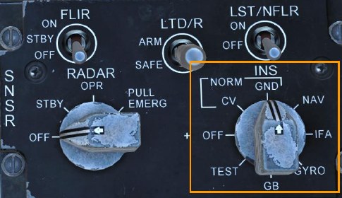
CV (Carrier Alignment). This is the primary alignment mode onboard an aircraft carrier.
GND (Ground Alignment). This is the primary alignment mode on an airfield.
NAV (Inertial Navigation). This operational mode is used on aircraft without Global Positioning System (GPS) equipment installed.
IFA (Aided INS / Inflight Alignment). In Aided INS (AINS) Mode, the INS and GPS data is integrated to provide the best navigation data. This is the primary operating mode for aircraft with GPS. This selection also enables an Inflight Alignment mode if alignment is lost during flight.
Alignment Procedure
A full INS alignment should be accomplished prior to every flight. This is normally begun just after engine start and avionics power-up to allow time for the full alignment to complete prior to taxi.
-
Verify the Parking Brake is set.
Releasing the parking brake before alignment is complete may result in an invalid alignment. The alignment will need to be reinitialized.
-
INS Mode Selector Knob - GND on an airfield or CV on a carrier.
The alignment status may be monitored on the HSI page.
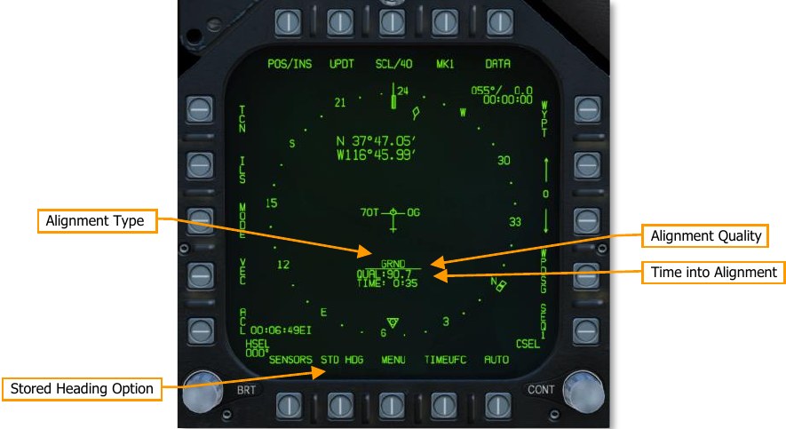
Alignment Type. This identifies the alignment mode being used. Possible types include GRND (ground alignment), CV RF (carrier alignment with position datalinked from ship), CV CBL (carrier alignment with position provided by cable from ship), CV MAN (carrier alignment with position manually entered).
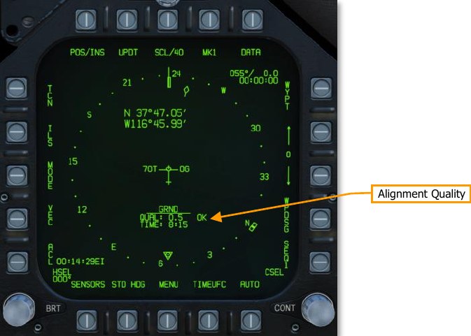
Alignment Quality. Initially, NO ATT will be displayed as the INS is calibrated for level. After calibration, a number estimating the accuracy of the present position is displayed. When an acceptable level has been reached, OK is displayed next to the QUAL number.
Time into Alignment. This starts to count up when the alignment begins.
Stored Heading Option. Selecting Stored Heading after the alignment begins may allow a faster INS alignment in certain situations. This can be useful for “scramble” missions or for situations when your play time is limited.
This alignment assumes a full gyrocompass alignment was already performed before the aircraft was last shut down and the aircraft has not been moved. The previously computed true heading is stored and used to give the alignment process a head start. The alignment then progresses as with a normal alignment.
-
Monitor alignment progress and switch INS knob to IFA (with GPS) or NAV (without GPS) when OK is displayed.
HSI Page
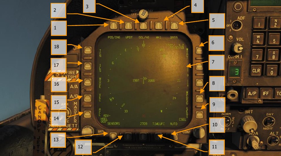
Regardless of navigation method, the HSI has the following options and indicators. Option buttons for the main HSI include:
-
POS/XXX Option. The POS Option button determines the position keeping source. Pressing this Option Button displays the four options along the top of the DDI with an HSI option button to return to the main HSI page without making a change.
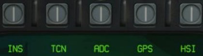
Figure 46. Position Keeping Source Selection - AINS. The inertial navigation system (aided by the GPS) is used as the navigation source.
- TCN. The active TACAN is used as the navigation source. The TACAN’s position must be in the onboard TACAN database (see TCN (TACAN) Sublevel).
- ADC. The air data computer and attitude heading reference system (ADC and AHRS) are used as the navigation source. This is a backup mode that is used when the INS fails. Accuracy degrades steadily over time.
- GPS. The GPS is used as the navigation source directly, without reference to the INS.
-
UPDT Option. Performs a preset position update. (N/I)
- SCL Option. This options allows selection of the range scale of the HSI. Successive presses of this button select and then wrap ranges of 5, 10, 20, 40, 80, and 160 miles. The selected scale is indicated right of the SCL legend.
- MK Option. Pressing the MK option button saves a markpoint at the location of the aircraft when the button was pressed. Up to nine markpoints can be created. After the ninth, the first markpoint will be over-written, and so forth.
- DATA Option. With either TCN or WYPT selected as the navigation method, pressing the DATA button will display a sublevel with additional information about the aircraft, selected TACAN and selected Waypoint. See DATA section below.
- WYPT Option. When selected and box, steering information is presented regarding the selected waypoint. See Waypoint Navigation.
- Waypoint / Markpoint Selection. The number between the two arrows is the selected waypoint, and the up arrow selects the next waypoint in the waypoint sequence and the down arrow selects the previous waypoint. At the end of the waypoint sequence, markpoints are available in sequence.
- WPDSG Option. Pressing the WPDSG designates the current navigation point as a target waypoint (TGT). When a waypoint is designated as a target, the WPDSG legend is removed and the WYPT legend changes to TGT. HUD symbology also reflects the change to be a target location.
- SEQ # Option. When selected and boxed, all waypoints of the sequence are displayed on the HSI and dashed lines connect them in sequence. Successive presses of this button cycle through the sequences. The Hornet can store three sequences. See Waypoint Navigation.
- AUTO Option. When selected and boxed, automatic sequence steering to the next waypoint is enabled. WYPT must be selected as the navigation method.
-
TIMEUFC Option. Selecting this option allows time selection options from the UFC. These include SET, ET (elapsed time) and CD (count down). Upon selecting (boxing) this option button, the UFC lists the time options to display on the HSI and HUD.
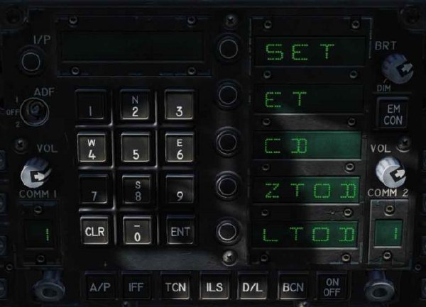
Figure 47. TIMEUFC Options on UFC SET. Displays the date.
ET. Starts incrementing time in minutes and seconds up to 59:59. Press the UFC ENT button to start the counter and successive presses of the ENT button will pause and start the counter.
CD. The countdown timer starts to decrement time in minutes and seconds, starting from 06:00. Upon selection of the CD option, pressing the ENT button starts the timer and successive presses of the ENT button pauses and start the counter.
ZTOD. When selected, the Zulu time of day is displayed.
LTOD. When selected, the local time of day is displayed. (N/I)
Note that ET and CD are mutually exclusive and ZTOD and LTOD are mutually exclusive.
-
MENU Option. Displays the TAC menu page.
- SENSORS Option. When enabled, aerial targets detected by the radar in range and azimuth are displayed on the HSI. (Coming later in early access)
- ACL Option. Automatic carrier landing (ACL)is selected as the navigation method. (N/I)
- VEC Option. LINK 4 Vector is selected as the navigation method. (N/I)
- MODE Option. Pressing the MODE option button displays sublevel options along the left side of the HSI. These include T UP (HSI is oriented to the flight track is always pointed towards the top of the HSI display), N UP (true north is always at the top of the display), DCTR (de-center placed the aircraft symbol at the bottom of the display), MAP (enable or disable moving map), and SLEW (N/I).
- ILS Option. ICLS is selected as the navigation method. (N/I)
- TCN Option. TACAN is selected as the navigation method. See TACAN Navigation.
Waypoint Navigation
How to Navigate Using Waypoints
- Select HSI from the SUPT DDI page
- Select the WYPT Option Select Button
- Use the Up and Down arrows to select waypoint as indicated between the arrows
- Fly to the waypoint based on HSI and HUD command steering indicators
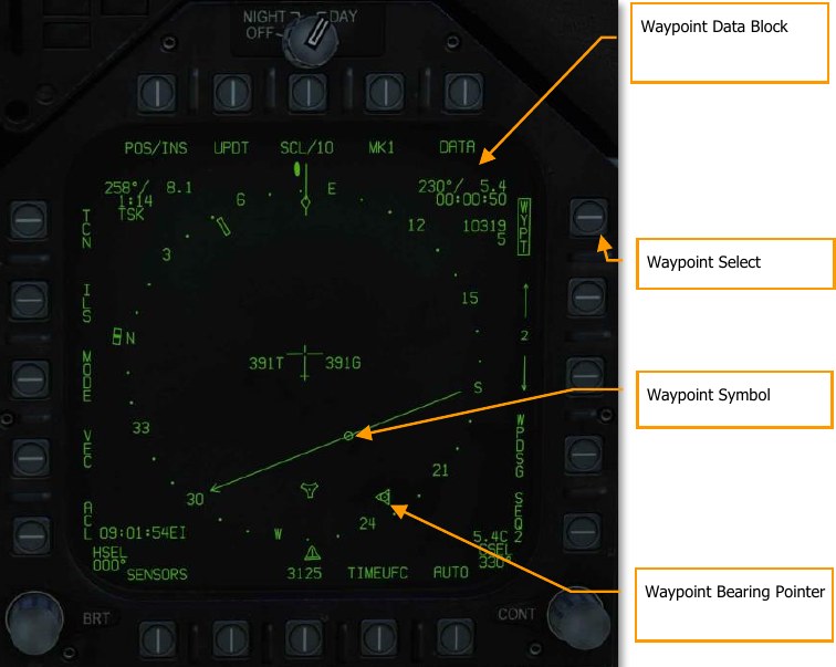
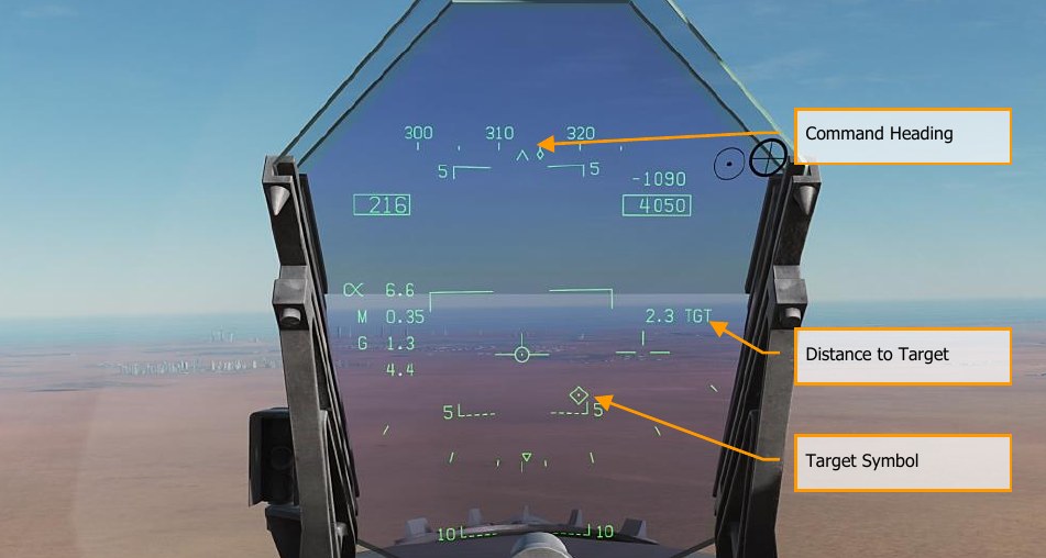
Waypoint navigation consists of a series of navigation points to create a navigation sequence. This allows point-to-point steering along the sequence using automatic (AUTO) sequencing. Any waypoint can also be designated as a target point (TGT) using the WPDSG option. Additionally, up to nine markpoints can be created that can also act as waypoints. Command heading, distance, and time to reach the selected waypoint is provided on the HSI Waypoint Data Block and HUD.
Waypoint steering is selected by pressing the WYPT option button on the right side of the HSI. Below are increment and decrement arrows to select the steer-to waypoint as indicated between the arrows.
In the top right of the HSI, the bearing to, distance to and time remaining to reach the selected waypoint are displayed in the Waypoint Data Block. Inside the compass rose, the waypoint bearing indicator and waypoint symbol provide heading steering information.
Additional waypoint steering is provided on the HUD.
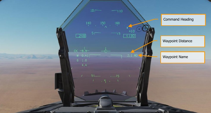
While in waypoint navigation steering and a waypoint selected, the WPDSG (waypoint designate) option button on the right side of the HSI can be pressed to change the selected waypoint to a target point. On the HUD, the target appears as a Target Designation diamond.
Time on Target (TOT) Navigation
Often in combat operations, it is vital to hit your target at a precise time in order to best coordinate with other friendly forces. Based on a Time on Target, or TOT, using Zulu time, the Hornet can provide you guidance to reach your target at the entered TOT.
To do so, following these steps:
-
Select Horizontal Situation Indicator (HIS) page from any display and then select the DATA / WYPT page. Along the bottom portion of the DATA page are blank fields for the desired time on target Zulu time, the ground speed from the initial point to the target point, and the waypoint that will serve as the target from which the TOT will be calculated.
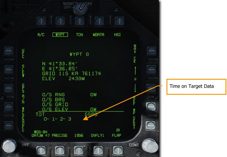
Figure 51. Time on Target Data Fields -
TOT Entry. First, we will enter the desired TOT. To do so, first press the WPSEQUFC pushbutton 1. This will then display GSPD (ground speed), TGT (target), and TOT (time on target) in the top three Option Select Windows. Upon pressing the TOT Option Select Button, the TOT indication on the Option Select Window will be colonized. Using the UFC Keypad, enter the hour:minute:second for the TOT based on Zulu time. The format is HH:MM:SS, and once you then press the ENT button on the UFC, the set TOT will then be displayed on the DATA / WYPT page.
Note that current Zulu time is generally displayed in the bottom left corner of the HUD.
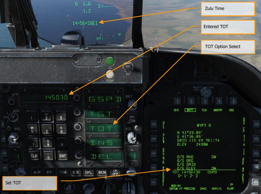
Figure 52. Time on Target Data Entry -
GSPD Entry. Next, we will enter the airspeed in calibrated knots that the aircraft will fly the leg between the Initial Point (waypoint before the target point) and the target point that will also serve as the TOT point. Select GSPD from the UFC Option Select Window to colonize it, and then enter the desired airspeed using the UFC keypad. Upon then pressing the ENT button on the UFC, the GSPD value on the DATA / WYPT page will be filled in.
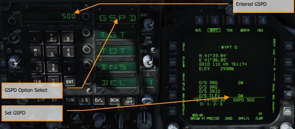
Figure 53. Ground Speed Data Entry -
TGT Entry. The final step is to designate the waypoint that will act as the target point from which the TOT will be calculated. Along the bottom of the DATA / WYPT page, the waypoints that comprise the selected sequence are listed. As before, select TGT from the UFC Option Select Window to colonize it and then use the UFC keypad to enter the number of the desired waypoint and then press the UFC ENT button. This will then box (set) the selected waypoint in the sequence.
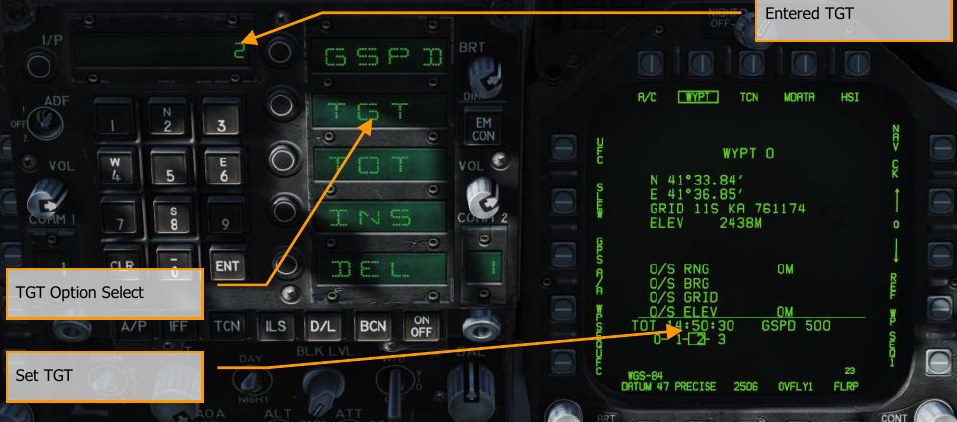
Figure 54. Target Data Entry With all elements set for a TOT calculation, a caret will appear below the airspeed box on the HUD, with a vertical line centered below the box. This is your early/late indication. If the caret is left of the line, you are too slow and must speed up to meet the TOT. If however the caret is to the right of the line, you are too fast and must slow down to meet the TOT. Ideally, you want the caret centered on the line to meet your TOT.

Figure 55. Time on Target HUD Indication
Modifying a Waypoint
During a mission, you may find the need to modify an existing waypoint, the most common being an adjustment of the waypoint’s elevation to match the ground elevation. To do so, select the HSI / DATA / WYPT page and note the chain of waypoints listed at the bottom of the page that comprise the waypoints of the selected sequence. For example: 0-1-2-3-4-5-6
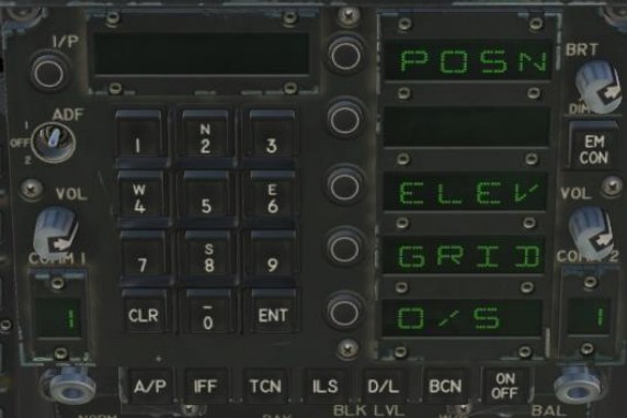
By pressing pushbutton 5, the UFC Option Select Windows display POSN (position), ELEV (elevation), GRID, and O/S (offset). To select a waypoint to modify, use the up (pushbutton 12) and down (pushbutton 13) arrows.
- POSN. By selecting Position, you may enter the Latitude and Longitude using the UFC keypad.
- ELEV. Once the Elevation option is selected, you can enter a new waypoint elevation in either feet or meters.
- GRID. This option lets you enter a waypoint position in MGRS coordinates. See Entering GRID Coordinates, below.
- O/S. This option lets you offset the waypoint by a bearing, distance, altitude, or grid. See the next section.
When complete, press the UFC ENT button.
Offset Aimpoints
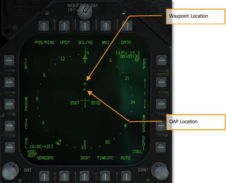
Offset aimpoints (OAPs) are used to mark locations relative to a waypoint. You can designate the waypoint or the offset aimpoint and receive steering and employment cues relative to either.
Creating an Offset Aimpoint
To add an offset aimpoint, first select the HSI / DATA / WYPT page, then press the pushbutton labeled UFC. The UFC waypoint options will appear:
Press the button next to “O/S”. The offset menu will appear:
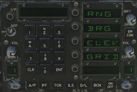
Press the button next to “RNG”:
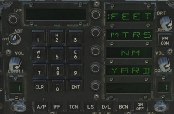
Press the button next to a unit of measure, then enter the range from the waypoint to the offset aimpoint, and press ENT.
Next, press the button next to “BRG”:
Select either true or magnetic bearing, and then enter the bearing from the waypoint to the offset aimpoint in degrees. Enter “0” for due north. Press ENT, then press the button next to “ELEV”:
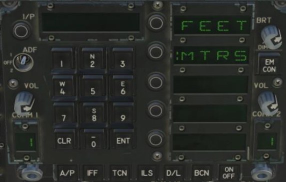
Select either feet or meters, then enter the elevation difference from the waypoint to the offset aimpoint. For example, if the offset aimpoint is 25 feet lower than the waypoint, enter “-25”. Press ENT.
You can also create an offset aimpoint based on an MGRS coordinate by pressing the button labeled “GRID” on the UFC menu. Doing so will display the grid format on the right DDI:
See Entering GRID Coordinates for more information.
Once the offset aimpoint has been configured, the DATA page of the HSI will display the offset aimpoint data:
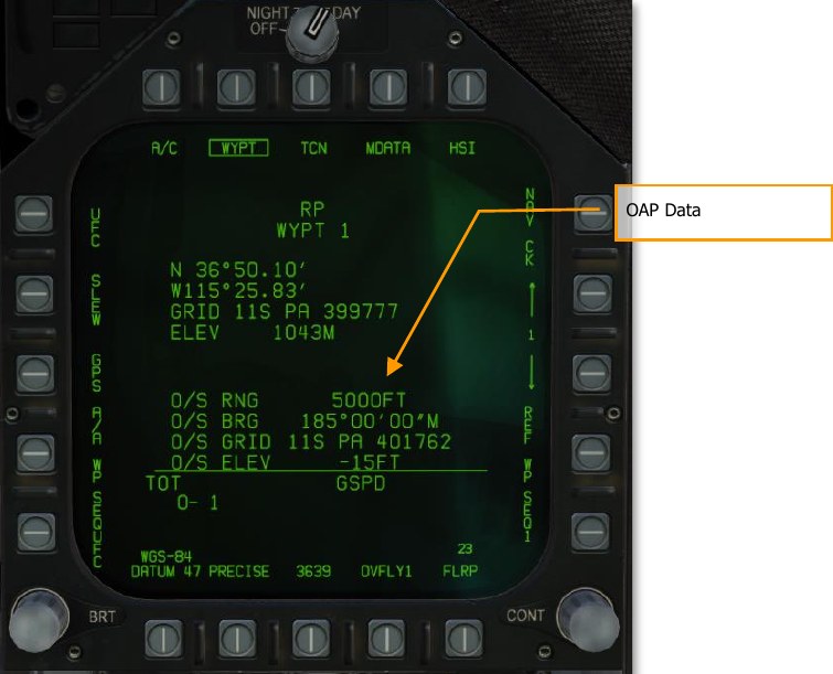
Using Offset Aimpoints
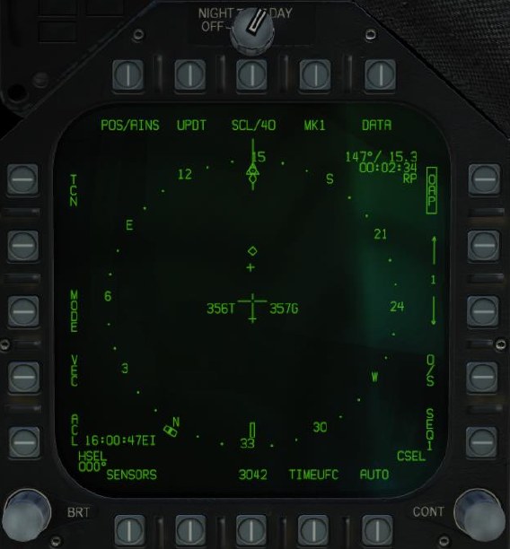
When a waypoint with an offset aimpoint is selected on the HSI, both the waypoint and the offset aimpoint are shown, and the text “OAP” appears instead of “WYPT” at PB10:
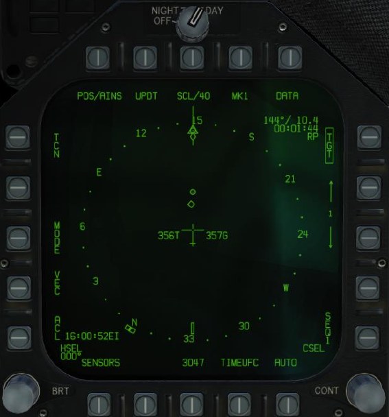
Boxing WPDSG (PB14) designates the waypoint but continues to display the offset aimpoint:
The label for PB14 changes to “O/S”. Pressing this pushbutton designates the offset aimpoint:
Adding or Deleting a Waypoint
At any time, waypoints can be added or deleted to a waypoint sequence. This is done from the HSI / DATA / WYPT page.
- To add a waypoint: Press pushbutton 1, WP SEQUFC, and then the INS Option Select Button on the UFC. Use the keypad to enter the number of the waypoint to add and then press the UFC ENT button. The new waypoint will then be added to the end of the selected waypoint sequence. You can only add the same waypoint to a sequence once.
- To delete a waypoint: Press pushbutton 1, WP SEQUFC, and then the DEL Option Select Button on the UFC. Use the keypad to enter the number of the waypoint to delete and then press the UFC ENT button. The new waypoint will then be removed from the selected waypoint sequence.
Inserting a Waypoint
To rearrange a sequence or add a new waypoint within a sequence, the insert function can be used. This is different than simply adding a waypoint which adds it to the end of a sequence. This can be done from the HSI / DATA / WYPT page.
From the WYPT page, select WP SEQUFC on pushbutton 1. Then, select INS from the UFC Option Select Window.
- Use the UFC keypad to enter the number of the waypoint in which you wish to insert a new waypoint to the right of in the sequence, and then press UFC ENT. You can only add the same waypoint to a sequence once.
- Use the UFC keypad to enter the number of the waypoint you wish to insert to the right of the waypoint you just designed, and then press UFC ENT.
The inserted waypoint will now appear in the active waypoint sequence to the right of the waypoint you designated.
Entering GRID Coordinates
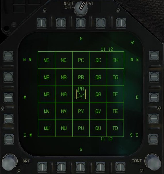
The F/A-18 can enter waypoint or target coordinates in Military Grid Reference System (MGRS) format. When editing grid coordinates, grid zones are shown on the right DDI, in the Square Identification Grid Format, which is a north-up display of grid squares around your current position.
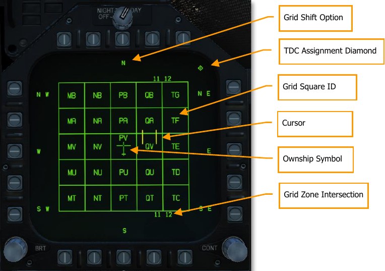
Grid Shift Option. Slew the TDC over a Grid Shift Option and press the TDC, or press the pushbutton adjacent the Grid Shift Option, to shift the grid by one square in that direction.
TDC Assignment Diamond. Shown if the TDC is assigned to this DDI.
Grid Square ID. The two-letter designator of a 100×100-km grid square.
Cursor. The target designator cursor.
Ownship Symbol. Your present location and heading.
Grid Zone Intersection. Displayed at the borders between grid zones. Shows the numeric east/west part of a Grid Zone Designation (GZD), such as the “11” in “11S”. In the image above, the second vertical line from right marks the border between the 11S grid zone and the 12S grid zone.
To enter a grid coordinate:
- From the DATA/WYPT page, press the pushbutton labeled UFC (PB20).
- On the UFC, press the Option Select Button labeled GRID. The Square Identification Grid format shows on the right DDI.
- Verify that TDC is assigned to the right DDI (the TDC Assignment Diamond is shown).
- Using the TDC, slew the cursors over the appropriate grid square. You can press the pushbuttons adjacent to each of the cardinal directions to shift in that direction. You can also slew the TDC cursor over a cardinal direction and press the TDC cursor to shift in that direction.
- Once you have slewed to the grid square, press the TDC. The grid square will be underlined. After a short pause, the MPCD will return to the WYPT display. (The old coordinates, including the old grid square, will still be displayed at this point.)
- Enter the six-digit easting and northing on the UFC. (If PRECISE is boxed, enter the ten- digit easting/northing.)
- Press the UFC ENT button. The WYPT page will be updated to reflect the new coordinates.
TACAN Navigation
The ARN-118 TACAN system provides relative bearing and/or slant range distance to a selected TACAN station (land, ship, or aircraft). TACAN range depends on aircraft altitude Line of Sight (LOS) to the station but can have a maximum range of 200 miles for an airborne station and 390 miles for a surface station. Each TACAN station has a three-letter identifier which is used to identify the beacon and is displayed on the HSI and HUD when using TCN steering.
To use TACAN steering:
- Select TCN from the UFC
- Press X or Y of the desired channel from the UFC Option Select Window / Button
- Turn on the TACAN by pressing the ON/OFF button on the UFC
- Press CLR (Clear) on the UFC keypad to clear the scratchpad
- Using the UFC keypad, enter the desired TACAN channel and then press the ENT button on the UFC
- Select TCN on the HSI display
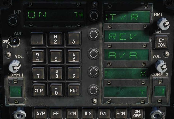
TACAN modes from the UFC include:
- T/R (Transmit / Receive). Computes bearing, and measures slant range from the selected TACAN station.
- RCV (Receive Only). Only bearing information from the selected TACAN station is computed.
- A/A (Air-to-Air TACAN). Computes range for up to five airborne TACAN stations.
- X. Selects the X band option.
- Y. Selects the Y band option.
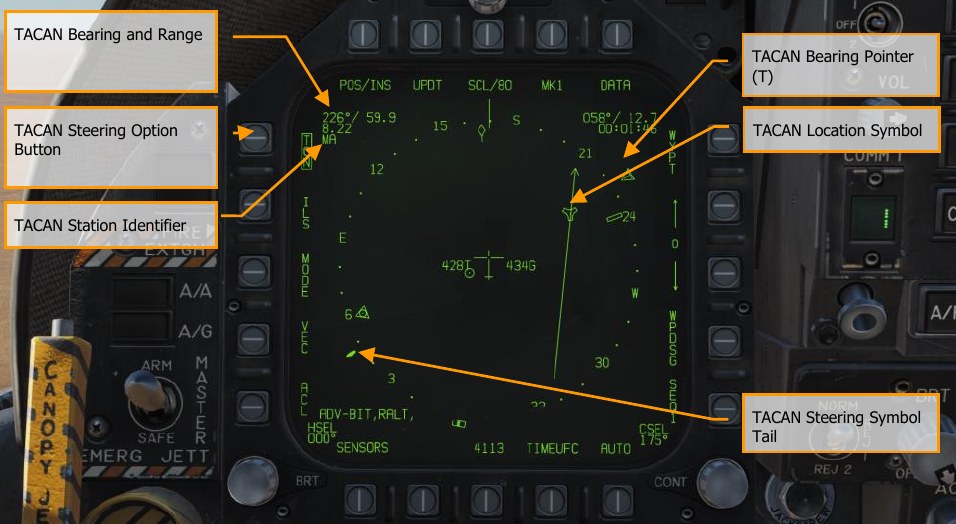
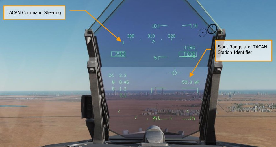
With TACAN steering selected with a valid TACAN station channel, steering to the selected station is provided on both the HSI and HUD as follows:
TACAN Yardstick
A very useful function of the air-to-air TACAN to find and keep formation with other aircraft is what’s termed “yardstick”. Although the datalink combined with the SA page largely eliminates the need for this, yardstick can still prove useful if the datalink is inoperative.
It is important to remember that TACAN yardstick will only provide range information between you and the other aircraft.
To enable TACAN yardstick:
- Set TACAN to A/A mode on UFC
- Set a TACAN channel 63 channels higher than the TACAN channel of the other aircraft, or have the other aircraft set their TACAN 63 channels above yours. One aircraft should be between 1 and 63 X or Y and the other(s) 63 channels higher from that. Note: be careful to avoid TACAN channels already in use by airfields and aircraft carriers and channels 68 and 69 due to datalink conflict.
Once set up, enable TCN navigation on the HSI and note that the heading needle will spin, due to the lack of bearing information. However, you will now have a distance indication. By altering your heading and noting the range increase or decrease, you can often determine the general heading of the other aircraft.
Also note that TACAN yardstick can work between any aircraft with A/A TACAN, it does not need to be only between Hornets.
DATA Option Sublevel
Upon selecting the DATA option button from the top of the HSI page, the DATA sublevel page is displayed with further sublevels for A/C (aircraft), WYPT (waypoint), and TCN (TACAN). The HSI pushbutton returns the MPCD/DDI to the main HSI page.
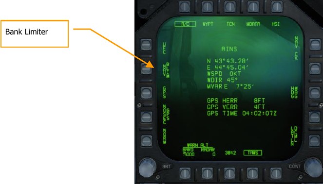
A/C (Aircraft) Sublevel
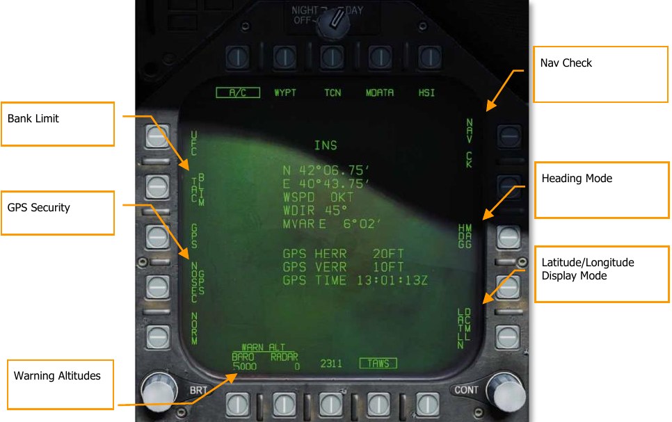
The center of the display shows aircraft latitude and longitude, wind speed and direction, and magnetic variation. Below that the horizontal and vertical GPS error is displayed, as well as the current GPS clock time.
Bank Limit. Sets the maximum bank that the autopilot will command in CPL (coupled) mode. Cycles between NAV (maximum 30° bank) and TAC (maximum 60° bank).
GPS Security. When unboxed, the GPS receiver will use encrypted GPS signals only. When boxed, both encrypted and unencrypted GPS signals are used. Unencrypted GPS is susceptible to spoofing. (N/I)
Warning Altitudes. Displays the barometric or radar warning altitude. When passing through this altitude, an aural “ALTITUDE” alert will sound. Pressing the adjacent pushbutton allows you to edit the warning altitude on the UFC. The barometric altitude can be set up to 25,000 feet and the radar altitude up to 5,000 feet. Setting either altitude to zero disables the alert for that setting.
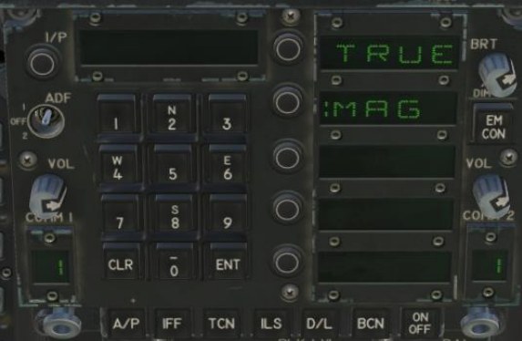
Heading Mode. Cycles between magnetic north and true north. This setting affects the display of headings on the HSI, the HUD, the radar, and many other formats. When true north is selected, a “T” or “TRUE” appears next to any heading shown on most displays. True north is used in the northern or southern areas of magnetic unreliability (AMU) near the north and south magnetic poles. When using TACAN navigation in true heading mode, the onboard TACAN database is used to lookup a station’s magnetic variation. If the TACAN station is not in the TACAN database, TACAN courses will reference magnetic north regardless of the selected heading mode.
Magnetic heading is sensed by the aircraft; true heading is derived from magnetic heading using a magnetic variation database. If the INS fails and the aircraft’s position is not reliably known, true heading is not available.
LAT / LONG Option. Toggles between degrees-minutes-decimal display (DCML) and degrees- minutes-seconds display (SEC) of latitude and longitude. If PRECISE is boxed under the WYPT page, additional decimal values will be added.
WYPT (Waypoint) Sublevel
The following items are functional in this early access version:
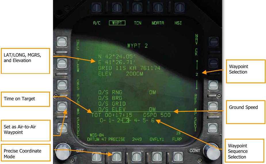
Waypoint, LAT/LONG, MGRS, and Elevation. At the top of this data block, the selected waypoint is displayed. Below is listed the waypoint:
- Latitude and longitude
- MGRS coordinate termed GRID
- Elevation in meters
PRECISE Option. Latitude and Longitude is entered as Degrees/Minutes/Hundredths (LATLN DCML), or Degrees/Minutes/Seconds (LATLN SEC). With PRECISE unboxed, LAT / LONG is entered either as Degrees/Minutes/Hundredths (LATLN DCML) or Degrees/Minutes/Seconds (LATLN SEC). With PRECISE boxed, LAT / LONG is entered either as Degrees/Minutes/Ten Thousandths (LATLN DCML) or Degrees/Minutes/Seconds/Hundredths (LATLN SEC). Actuating the LATLN XXXX option toggles between the selection of LATLN DCML and LATLN SEC. The selected LATLN format is reflected on all displays and UFC formats throughout the cockpit.
Air-to-Air Waypoint. Pressing pushbutton 2 sets the selected waypoint as the air-to-air waypoint (aka Bullseye). See Air-to-Air Waypoint section.
Waypoint Selection. Pressing pushbutton 12 increments the waypoint and pressing pushbutton 13 decrements the selected waypoint. The current waypoint is displayed between pushbuttons 12 and 13 and at the top of the waypoint data block. Ground Speed. Entered ground speed for last leg to the waypoint set as the TGT.
Waypoint Sequence Selection. A listing of the waypoints in the selected sequence (1, 2, or 3). The selected target (TGT) waypoint is boxed.
Time on Target. The inputted time on target in reference to Zulu time.
TCN (TACAN) Sublevel
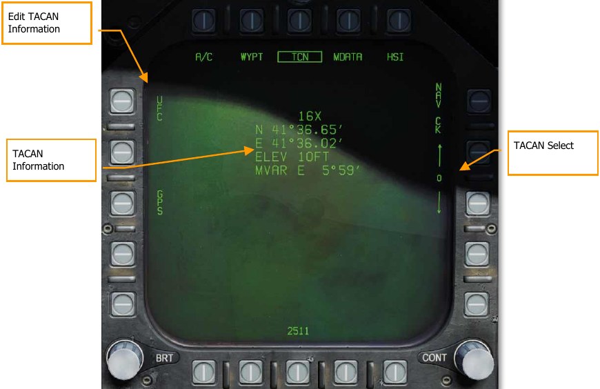
The TCN sublevel allows you to view and edit TACAN stations in the aircraft’s onboard TACAN database. The TACAN database stores the location, elevation, and magnetic variation of nearby TACAN stations. While the aircraft can navigate to any TACAN station, whether or not it is in the TACAN database, having the TACAN station in the database enhances the aircraft’s ability to use TACAN as a position source or display the TACAN on the moving map.
Up to ten TACAN stations can be stored in the onboard database. In DCS, the database is pre-loaded with the TACANs in the current theater.
TACAN Select. Selects from one of up to ten TACAN stations in the database. Unused database slots are initialized to “1X” with zeroized position, elevation, and magnetic variation.
TACAN Information. Displays the position, elevation, and magnetic variation for a TACAN in the database.
Edit TACAN Information. Pressing PB5 allows the pilot to edit the selected TACAN station (or to add a new one if an empty slot is selected). Editing options are displayed on the UFC:
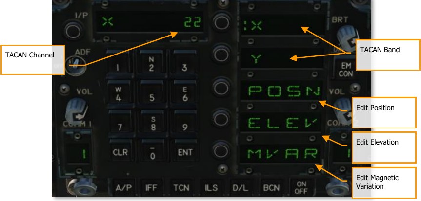
TACAN Channel. Displays the TACAN channel. To change the TACAN channel for this database entry, use the keypad to enter the new channel number and press ENT.
TACAN Band. Select the option select button adjacent either “X” or “Y” to change the TACAN band.
Edit Position. Select this option select button to edit the latitude and longitude of the TACAN station. First enter the latitude using the keypad, then press ENT, then enter the longitude, then press ENT again.
Edit Elevation. Select this option select button to edit the elevation of the TACAN station. First select either FEET or MTRS (meters) to colonize the proper units, then use the keypad to enter the new elevation and press ENT.
Edit Magnetic Variation. Select this option to change the TACAN station’s magnetic variation. Use the keypad to enter the new magnetic variation and press ENT.
Automatic Direction Finder (ADF) Navigation
A third method of navigation is Automatic Direction Finder (ADF). ADF uses radionavigation based on beacons in the 108.0 to 400.0 MHz range. Either radio in the Hornet can be tuned to the desired ADF channel and receiving steering information for the selected beacon. However, no range information is given. The bearing to the selected ADF beacon is displayed as a circle on the outer periphery of the HSI compass rose.
How to Navigate Using ADF Beacons
- Select either 1 (COMM 1) or 2 (COMM 2) from the ADF switch on the UFC
- Rotate the channel selector of the selected ADF switch to the Manual (M)
- Using the UFC keypad, enter the frequency of the desired ADF beacon into the UFC Scratchpad and press ENT on the UFC
- The selected ADF beacon should now appear on the HSI as a circle and the ADF code will be heard (adjusted through the Volume Panel)
Note that this ADF cannot be used with most non-directional beacons (NDBs), which transmit on frequencies between 190 and 1750 kHz. It can be used to navigate to VHF omnidirectional range (VOR) stations, as those typically transmit on frequencies between 108 and 118 MHz.
Additional HSI Symbology
In addition to the HSI symbols described above, other symbols are present to assist in navigation.
These include:
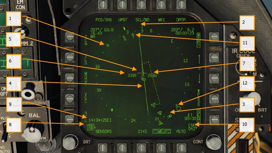
- Compass Rose. 360° compass with cardinal directions. The compass rose is referenced to aircraft track by default, to magnetic north when “N UP” is selected under the MODE submenu, or to true north when “N UP” is selected under the MODE submenu, and TRUE heading is selected under the DATA → AIRCRAFT submenu.
- Lubber Line. A line marked on the compass rose that indicates aircraft heading.
- Heading Select Marker. Heading marker on the compass rose to indicate set heading value as indicted in the Heading Select numeric indication.
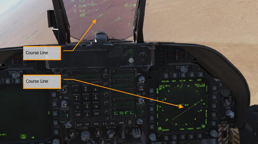
- Course Line. Set course line through the selected TACAN station or Waypoint and rotated to match the Selected Course numeric.
- Aircraft Symbol. Placed in the center or de-centered in the compass rose, this indicates the location of the aircraft.
- Ownship True Airspeed. True airspeed of your aircraft.
- Ownship Ground Speed. True ground speed of your aircraft.
- Selected Heading. Heading value set using the Heading Select Switch on the MPCD.
- Time. Time indication as selected from the TIMEUFC option button.
- Selected Course. Course value set using the Course Select Switch on the MPCD.
- Ground Track Pointer. Actual track of the aircraft over ground.
- Automatic Direction Finding (ADF Symbol). When ADF is selected to a valid frequency, this icon provides a heading cue to the selected ADF beacon. Not pictured.
Setting a Course
A course can be set using the Course Select Switch on the MPCD. The selected course value is then displayed on the HSI in the Course Select (CSEL) field and drawn through the selected TACAN or Waypoint. The Course Line has an arrow at the end that points in the direction of the set course. Pressing the Course Switch left and right allows the CSEL to be rotated to match the desired course. On the HUD, the selected course is displayed as a small arrow with two dots on either side to denote course offset. The arrow provides a horizontal situation indication relative to the Velocity Vector. The dots left and right of the arrow indicate 4° and 8° off course. The dots disappear when course error is less than 1.25°.
Note that the distance to the course line is displayed the CSEL indication. This is particularly useful when flying the correct downwind distance to the airfield or aircraft carrier of 1.1 to 1.3 nm.
Autopilot Relief Modes
The Hornet includes several autopilots modes that assist the pilot in flying the aircraft. The autopilot modes are displayed by pressing the A/P button on the lower portion of the UFC. The available autopilots modes are listed in the UFC Option Select Windows. Pressing an Option Select Button activates an autopilot mode. The modes include:
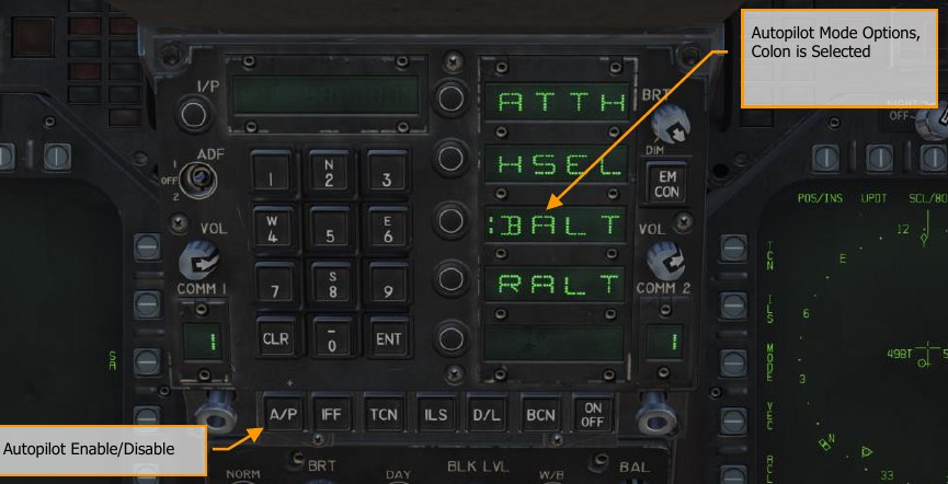
- Attitude Hold (ATTH). The aircraft will maintain the existing pitch and roll attitude between ±45° in pitch and ±70° in roll.
- Heading Select (HSEL). When enabled, the aircraft will turn to and fly the heading as set on the HSI.
- Barometric Altitude Hold (BALT). When engaged, the aircraft will maintain the current heading and barometric altitude between 0 and 70,000 feet.
- Radar Altitude Hold (RALT). When engaged, the aircraft will maintain current heading and radar altitude between 0 and 5,000 feet.
- Coupled Hold (CPL). This mode is available when TACAN or WYPT is the active navigation mode. When engaged, the aircraft will fly to the selected waypoint or TACAN station. The autopilot can also fly specific courses to a waypoint or station, or automatically fly to waypoints in a sequence.
Autopilot modes listed on the UFC are selected by pressing the Option Select Button next to the Option Select Window of the autopilot mode. When selected, a colon is displayed next to the autopilot name on the Option Select Window. Once selected, pressing the ON/OFF button on the UFC enables the mode. An A/P advisory is displayed on the left DDI when an autopilot mode is engaged. Autopilot is disengaged by pressing the Paddle Switch on the Control Stick.
Using Coupled Autopilot Mode
When in Coupled mode, the autopilot can fly to a waypoint or a TACAN station, can fly a specific course to a waypoint or TACAN station, and can automatically fly along a sequence of waypoints. Coupled mode only controls roll, not pitch. You can either control pitch yourself, or activate one of the pitch modes (BARO or RALT) together with CPL.
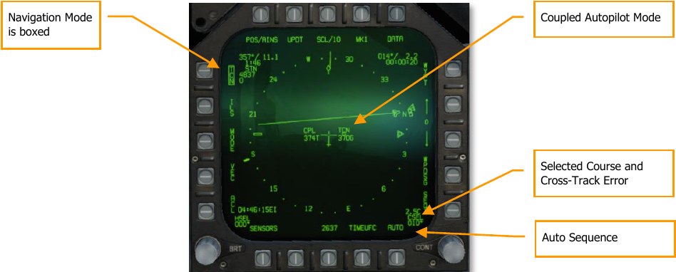
The active sub-mode of coupled mode is displayed on either side of the ownship symbol on the HSI, and on the right side of the HUD. “CPL TCN” is displayed when coupled to a TACAN, “CPL WYPT” when coupled to a waypoint, “CPL SEQ1” when coupled to waypoint sequence SEQ1 with AUTO boxed, and “CPL OAP” when coupled to an offset aimpoint.
If the autopilot has de-coupled because of something other than pilot-commanded disconnect (e.g., loss of TACAN signal), the HUD indicator will flash repeatedly. The flashing will continue until the paddle switch is depressed.
When coupled mode is active, moving the stick will temporarily override it.
Bank Limiter. Cycles the bank limiter between NAV and TAC modes. In NAV mode, autopilot commanded bank is limited to 30° when coupled. In TAC mode, the limit is 60°.
Flying Directly to a Waypoint or TACAN Station
To fly directly to a waypoint or a TACAN station (including a carrier TACAN):
- Select the waypoint using the HSI format or tune the TACAN station using the UFC. (Verify that the TACAN is on.)
- Activate the appropriate navigation mode. For waypoint navigation, box WYPT (PB 11). For TACAN navigation, box TCN (PB 5).
- Press the AP button on the UFC to show the autopilot options.
- Press the OSB adjacent “CPL” to activate coupled autopilot mode. A colon will appear (“:CPL”) to indicate that it is active.
Upon crossing the waypoint or TACAN station, the autopilot will transition to heading hold mode and continue flying the current heading.
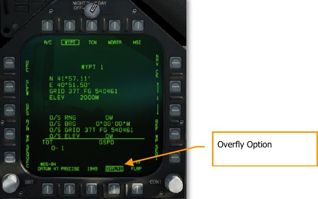
Overfly Option. This PB is labeled OVFLYX (where X is the current waypoint). When boxed, turn anticipation is inhibited. The aircraft will directly overfly the next steerpoint, and turn to intercept the outbound course only after crossing it. When boxed, the OVFLY option applies to all waypoints until unboxed.
Flying a Course To/From a Waypoint or TACAN Station
To fly a course to or from a waypoint or TACAN, follow the steps above, while also selecting a course using the CSEL switch or the UFC. The aircraft will turn to intercept the course (if not already established), and then turn to the fly the course once established. The course will be flown either inbound or outbound depending on the selected course direction. (Use the HSI to help visualize which direction the aircraft will fly after intercepting the course.)
After crossing the waypoint or station, the autopilot will continue following the same course outbound.
Flying Along a Sequence of Waypoints
When the autopilot is in coupled in WYPT mode, and the AUTO sequence option (PB 16) is boxed, the navigation system will automatically activate the next waypoint in the sequence upon crossing each waypoint. Use PB 15 to ensure the proper sequence is selected, and press PB 16 to box the AUTO option. When the autopilot is coupled in WYPT mode, the aircraft will automatically fly to each waypoint in the sequence.
Instrument Carrier Landing System (ICLS)
While real US Navy and Marine Corps Hornets are not equipped with Instrument Landing System (ILS) for airfield landings, they are equipped with the Instrument Carrier Landing System (ICLS). This operates much like a traditional ILS system, but it is only operational for US aircraft carriers.
Using the ICLS is a matter of setting up the correct aircraft carrier ICLS channel and following the localizer and glideslope beams to within visual distance of the IFLOLS.
Please use the following checklist for a successful ICLS approach.
How to Use ICLS
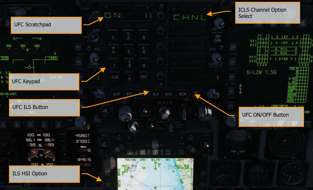
- Select ILS from the Up-Front Control (UFC) panel. The carrier ICLS channel will most often be listed in the mission briefing
- Press the ON/OFF UFC button on the UFC to turn on the ICLS
- Enter the desired carrier ICLS channel into the UFC scratchpad using the UFC keypad and then press the ENT button
- Select ILS on pushbutton 5 from the HSI. This will allow ICLS information to be displayed on the HUD and DDI HUD repeater page
- Fly to keep the vertical localizer and horizontal glideslope bars centered in the HUD. If the localizer is off-center, fly in the direction of the bar to center it. If the glideslope bar is above the velocity vector, you are too low. If it is below the velocity vector, you are too high.
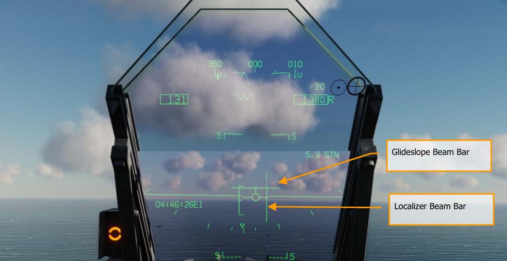
In the above example image, the pilot is left of the localizer (lineup) and below glideslope. Fly to keep the two bars forming a cross in the center of the velocity vector.