Heads-Up Display
The Heads-Up Display, or HUD, is one of your most important instruments and provides valuable information as to your aircraft flight performance and weapon / sensor information. In later sections of this guide, we will discuss aspects of the HUD that are specific to certain weapons and sensors, but the HUD does have a common set of information that is almost always displayed.
The HUD as pictured below is independent of aircraft Master Mode except for the bank angle scale, vertical velocity, and heading scale.
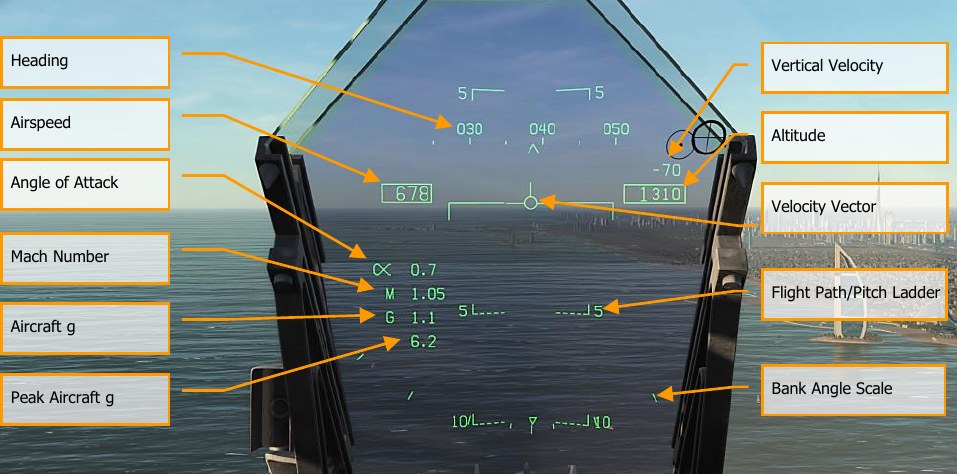
Heading. This 30°, moving heading scale displays the aircraft’s magnetic or true heading (set in HSI/DATA). The aircraft’s heading is indicated as the caret in the center of the scale. When true heading is selected, a “T” is placed below the heading caret.
Airspeed. Calibrated airspeed as determined by the Air Data Computer (ADC).
Vertical Velocity. Positive or negative aircraft altitude change in feet per minute.
Altitude. Barometric or radar altitude in feet as set by the ALT switch on the HUD control panel. When radar altitude is selected, an “R” is displayed next to the altitude box. If the radar altitude is invalid, a flashing “B” is displayed to indicate that barometric altitude is being used instead.
Angle of Attack. True angle of attack in degrees of the aircraft. Mach Number. Aircraft speed as Mach airspeed.
Aircraft g. Normal acceleration value of the aircraft.
Peak Aircraft g. Maximum achieved g over 4 g.
Velocity Vector. Represents the point toward which the aircraft is flying along the aircraft’s actual flight path. When not displaying accurate information, the symbol will flash. The Velocity Vector can be caged and uncaged to the center of the HUD with the cage/uncage button on the throttle.
Flight Path/Pitch Ladder. The vertical flight path angle of the aircraft as indicated by the position of the Velocity Vector on the Flight Path/Pitch Ladder. The aircraft’s pitch angle is indicated as the aircraft waterline on the Flight Path/Pitch Ladder.
Bank Angle Scale. With marks at 5°, 15°, 30° and 45°, rolling the aircraft to place the center caret in relation to these marks provides a bank angle reference.
Barometric Setting. The barometric altitude is displayed below the altitude box for five seconds when the barometric altitude is changed on the standby altimeter. It will also display if the aircraft is below 10,000 feet and at an airspeed less than 300 knots if previously above both values.
Ghost Velocity Vector. When the Velocity Vector is caged using the cage/uncage button on the throttle, the Ghost Velocity Vector is displayed and shows the true velocity vector of the aircraft. When caged, the pitch ladder and velocity vector will stay caged to the center of the HUD. As such, if you find the velocity vector and pitch ladder off-center on the HUD, it is due to yaw or wind. To center these, press the cage/uncage button on the throttle until caged and the Ghost Velocity Vector shows “true” velocity vector.